Nissan Micra Heater & Ventilation Component Layout - HVAC Duct Diagram (HA-3)
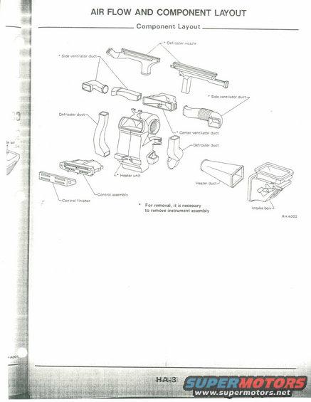
Exploded parts drawing of HVAC component layout showing heater unit, ventilator and defroster ducts, and control assembly.
This is a scanned page (HA-3) from a Nissan factory service manual section titled "AIR FLOW AND COMPONENT LAYOUT." The page presents an exploded-view diagram labeled "Component Layout" showing the heating/ventilation (HVAC) ductwork and components behind the instrument panel. Labeled components include the defroster nozzle, two side ventilator ducts, two defroster ducts, the center ventilator duct, the heater unit, the control assembly, the control finisher, the heater duct, and the intake box. Items marked with an asterisk (defroster nozzle, side ventilator ducts, center ventilator duct, heater unit) carry the footnote "For removal, it is necessary to remove instrument assembly," telling the reader that the dashboard/instrument assembly must be pulled to access those parts. The diagram carries the illustration reference code RHA002 and the page number HA-3, consistent with the Heater & Air Conditioner (HA) section of a Nissan service manual. A reader can learn how the interior HVAC air distribution parts fit together, what each duct is called, and which components require removal of the instrument assembly before they can be serviced or replaced. The document does not state a specific model year, model name, or part numbers.
Is this accurate? Sign in to help verify it.
Frequently asked questions
- What HVAC components are shown in the Nissan component layout diagram?
- The exploded view shows the defroster nozzle, side ventilator ducts (left and right), defroster ducts, center ventilator duct, heater unit, control assembly, control finisher, heater duct, and intake box.
- Which heater components require removing the instrument assembly?
- Items marked with an asterisk, the defroster nozzle, side ventilator ducts, center ventilator duct, and heater unit, require removal of the instrument assembly for their removal.
- What manual section and page is this diagram from?
- It is page HA-3 of the "Air Flow and Component Layout" section, with illustration reference code RHA002.
- Where does the intake box sit relative to the heater duct?
- In the diagram, the heater duct connects toward the intake box, which is shown at the far right side of the exploded layout.
Comments
More from this build











No comments yet.