Home/
Registry/
Suzuki/
Samurai/
1986-1995/
“Little Blue”/
Photo
supermotors.net/registry/media/420646
Suzuki Samurai Cruise Control Wiring Diagram - Shift & Clutch Switch Circuits
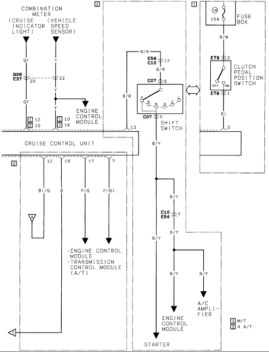
Factory wiring diagram linking the cruise control unit, combination meter, shift switch and engine/transmission control modules with wire codes.
This is a cruise control system wiring diagram (page 2 of a set, filed as Cruise2.gif) uploaded for a 1986 Suzuki Samurai. It shows the cruise control unit and its connections to the combination meter (cruise indicator light on a Gray wire and vehicle speed sensor on a Yellow wire, through connector G06/E37 pins 20 and 22), the engine control module, and the transmission control module (A/T). Manual transmission vehicles (legend [1]) use a clutch pedal position switch fed by a 15A fuse (position 18) in the fuse box via a Black/White wire, through connector E79 pins 2 and 1, returning on a Blue wire. Automatic transmission (4 A/T, legend [2]) vehicles use a shift switch (P-R-N-D-2-L) connected through connectors E54/C10 pin 12 and C07 pins 6 and 5, with a Black/Red wire in and Black/Yellow wire out. The Black/Yellow circuit branches to the A/C amplifier, engine control module, and starter. Cruise control unit connector [2] pins 12, 18, 17, and 7 carry Blue/Green, Black (ground), Pink/Green, and Pink/Blue wires respectively, the latter two going to the ECM and TCM. Wire colors, connector identifiers, and pin numbers throughout allow tracing and troubleshooting the cruise control circuits for both M/T and A/T configurations.
Is this accurate? Sign in to help verify it.
Frequently asked questions
- What fuse powers the clutch pedal position switch in this cruise control circuit?
- A 15A fuse in position (18) of the fuse box, feeding the clutch pedal position switch through a Black/White (B/W) wire to connector E79 pin 2.
- What wire colors connect the combination meter to the cruise control unit?
- The cruise indicator light uses a Gray (Gr) wire and the vehicle speed sensor uses a Yellow (Y) wire, passing through connector G06/E37 at pins 20 and 22.
- Which components does the Black/Yellow (B/Y) wire from the shift switch connect to?
- The B/Y wire from shift switch connector C07 pin 5 branches to the A/C amplifier, the engine control module, and the starter.
- How do the diagram's [1] and [2] markings differ?
- The legend states [1] applies to M/T (manual transmission, using the clutch pedal position switch circuit) and [2] applies to 4 A/T (4-speed automatic, using the shift switch circuit).
- What connector pins are used at the shift switch?
- The shift switch connects via connector C07: pin 6 carries the B/R input and pin 5 carries the B/Y output. Upstream, connectors E54/C10 pin 12 join the B/R circuit.
Comments
More from this build














No comments yet.