Home/
Registry/
Suzuki/
Samurai/
1986-1995/
“Little Blue”/
Photo
supermotors.net/registry/media/420644
Suzuki Samurai Starting/Cranking Circuit Wiring Diagram - M/T & A/T Starter
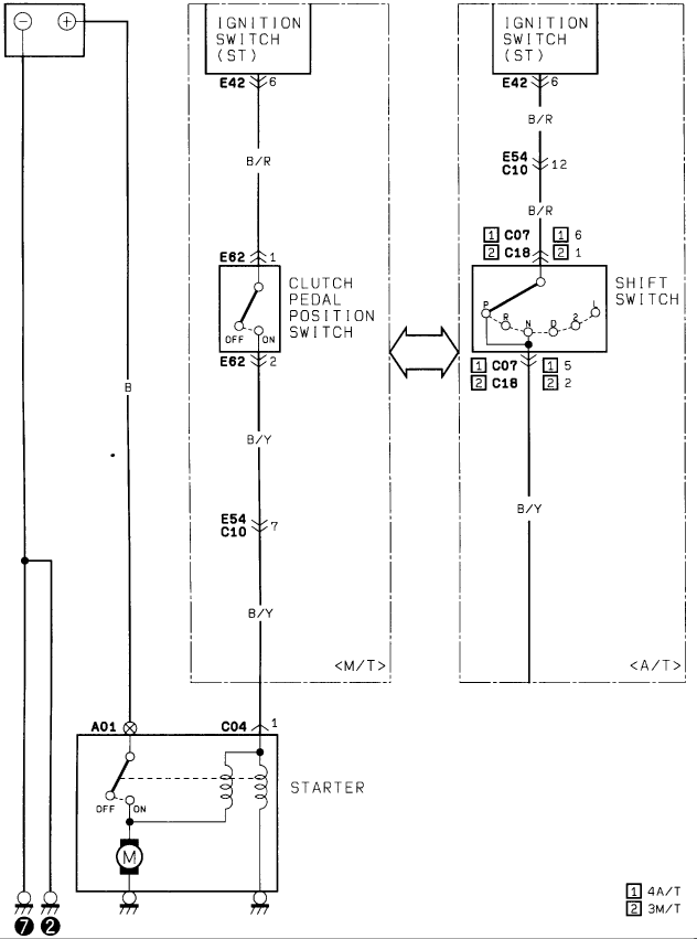
Factory starting-system wiring diagram routing the ignition switch through the clutch pedal and shift switches to the starter for M/T and A/T.
This is a starting (cranking) circuit wiring diagram, uploaded as one page of a factory-style wiring diagram set for a 1986 Suzuki Samurai. It shows current flow from the battery positive terminal (wire color B) to the starter assembly at connectors A01 and C04 pin 1, with the starter internally depicted as a solenoid switch (OFF/ON), pull-in/hold-in coils, and the motor (M), grounded at points labeled 7 and 2. Two parallel start-enable paths are shown: for manual transmission (M/T), the ignition switch ST terminal feeds through connector E42 pin 6 on a B/R (black/red) wire to the clutch pedal position switch at connector E62 (pins 1 and 2), then continues on a B/Y (black/yellow) wire through connector E54/C10 pin 7 to the starter solenoid. For automatic transmission (A/T), the same B/R feed passes through E54/C10 pin 12 to the shift switch (park/neutral positions P, R, N, D, 2, L) via connectors C07 or C18 depending on transmission type (legend: [1] = 4A/T, [2] = 3M/T), then exits on a B/Y wire to the starter. The diagram gives all connector numbers, pin numbers, and wire color codes needed to diagnose no-crank conditions.
Is this accurate? Sign in to help verify it.
Frequently asked questions
- What wire colors are used in the Samurai cranking circuit?
- B/R (black/red) runs from the ignition switch ST terminal to the clutch pedal position switch or shift switch, and B/Y (black/yellow) continues from those switches to the starter. A plain B wire feeds the starter directly from the battery positive terminal.
- What switch is in the starter circuit on manual transmission models?
- A clutch pedal position switch at connector E62 (pins 1 and 2), fed on a B/R wire from ignition switch connector E42 pin 6 and outputting on a B/Y wire through E54/C10 pin 7.
- What switch does the automatic transmission use to allow cranking?
- A shift switch with positions P, R, N, D, 2, L, connected through connector C07 (pins 6 and 5) for 4A/T or connector C18 (pins 1 and 2) for 3M/T, per the diagram's legend.
- Where does the starter connect in this diagram?
- The starter solenoid control wire connects at connector C04 pin 1, battery power at A01, and the assembly is grounded at points marked 7 and 2.
- What do the [1] and [2] boxes mean on the connector labels?
- Per the legend, [1] indicates 4A/T (4-speed automatic) and [2] indicates 3M/T applications.
Comments
More from this build














No comments yet.