Home/
Registry/
Suzuki/
Samurai/
1986-1995/
“Little Blue”/
Photo
supermotors.net/registry/media/420645
Suzuki Samurai Cruise Control Wiring Diagram - Actuator, Switches & Fuses
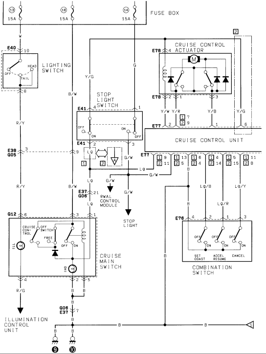
Factory cruise-control wiring diagram showing the cruise actuator, control unit, main switch and set/coast/resume combination switch circuits.
This document is page 1 of a two-page cruise control wiring diagram (filed for a Suzuki Samurai). It shows power feeding from three 15A fuses (positions 13, 18, and 14) in the fuse box to the cruise control system. Major components depicted include the lighting switch (connector E40), stop light switch (E41), cruise control actuator (E78) with its internal motor, solenoid, and diodes, the cruise control unit (E77) with pin assignments for two connector variants (marked [1] and [2]), the cruise main switch (G12) with FREE/OFF/ON positions and illumination bulbs, and the combination switch (E76) housing the SET/COAST, ACCEL/RESUME, and CANCEL buttons. The diagram also shows interconnections to the RWAL control module (via connector E37/G06 pin 21), the stop light circuit, and the illumination control unit. Wire colors are labeled throughout, including W, B/W, R/Y, R/G, Y/G, Y/W, Y/R, Y/B, G, G/W, Lg, Lg/B, Lg/R, and Lg/Y, along with connector pin numbers and two chassis ground points (9 and 10). A reader can trace power, switching, and control paths for diagnosing cruise control, stop light switch, and related illumination circuits.
Is this accurate? Sign in to help verify it.
Frequently asked questions
- What fuses power the cruise control circuit in this diagram?
- Three 15A fuses in the fuse box, positions 13, 18, and 14.
- What connector is the cruise control actuator on and what wire colors does it use?
- The cruise control actuator uses connector E78 (pins 4, 2, 1, 3) with wire colors Y/W, Y/R, Y/B, and Y/G, and contains a motor, solenoid, and diodes.
- Which switches are in the combination switch for cruise control?
- Connector E76 houses three switches: SET COAST (OFF/ON), ACCEL RESUME (OFF/ON), and CANCEL (OFF/ON), wired with Lg/B, Lg/R, and Lg/Y wires.
- How does the stop light switch connect to the cruise system?
- The stop light switch (connector E41, pins 4, 1, 2, 3) receives Y/G and G feeds and outputs Lg and G/W wires; the G/W wire goes to the cruise control unit, the RWAL control module (E37/G06 pin 21), and the stop light.
- What wire color feeds the illumination control unit from the cruise main switch?
- An R/G wire runs from the cruise main switch (connector G12) to the illumination control unit.
Comments
More from this build














No comments yet.