Home/
Registry/
Suzuki/
Samurai/
1986-1995/
“Little Blue”/
Photo
supermotors.net/registry/media/420648
Suzuki Samurai Rear Defogger Wiring Diagram - Defroster Switch & Fuse Circuit
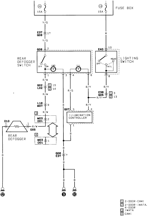
Factory wiring diagram of the rear defogger circuit, defogger switch, lighting switch and illumination controller with wire color codes.
Part of 1986-1995 Suzuki Samurai Wiring Diagrams
This document is a wiring diagram for the rear window defogger (defroster) circuit, apparently from a Suzuki factory service manual. Power is supplied through two 15A fuses in the fuse box (positions 21 and 13). Fuse 21 feeds the rear defogger switch via a Yellow/Green (Y/G) wire through connector E37/G06 pin 17 and connector G08 pin 2. The rear defogger switch contains an OFF/ON contact plus an indicator (IND) lamp and illumination (ILL) lamp. The switched output leaves on a Red/White (R/W) wire through connectors G02/L02 (pin 15 or 14 depending on body style), L16/M07 pin 9, and M03/O01 (pin 2 or 1 depending on assembly plant) to the rear defogger grid (connectors O10 and O05), which grounds through a Black (B) wire at ground point 12. Fuse 13 feeds the lighting switch (connector E40 pin 10, White wire); its TAIL output (Red/Yellow, via E38/G05) provides dash illumination, routed through an illumination controller (connector G07) that dims the switch's ILL lamp. Grounds return through G06/E37 pin 7 to ground points 9 and 10. A legend distinguishes variants: 2-door CAMI-built, 2-door IWATA-built, 4-door, IWATA, and CAMI assembly plants.
Is this accurate? Sign in to help verify it.
Frequently asked questions
- What fuses power the rear defogger circuit?
- Two 15A fuses in the fuse box: fuse position 21 feeds the rear defogger switch, and fuse position 13 feeds the lighting switch for illumination.
- What wire color carries power from the rear defogger switch to the defogger grid?
- Red/White (R/W), running through connectors G02/L02, L16/M07 (pin 9), and M03/O01 to the rear defogger element.
- How does the defogger switch illumination get power?
- Through the lighting switch (TAIL position) via a Red/Yellow (R/Y) wire through connector E38/G05, with brightness handled by the illumination controller connected at G07.
- Where does the rear defogger grid ground?
- The grid grounds through a Black (B) wire to ground point 12; the switch and illumination controller circuits ground through connector G06/E37 pin 7 to ground points 9 and 10.
- What do the numbered legend boxes on the diagram mean?
- They indicate build variants: [1] 2-door CAMI, [2] 2-door IWATA and 4-door, [3] IWATA, [4] CAMI: different connector pins apply depending on the variant.
Comments
More from this build














No comments yet.