Home/
Registry/
Suzuki/
Samurai/
1986-1995/
“Little Blue”/
Photo
supermotors.net/registry/media/420651
Suzuki Samurai ECM Wiring Diagram - Engine Control Module, O2 & Cam Sensor
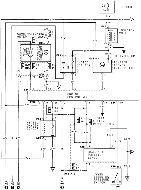
Factory engine-control wiring diagram linking the ECM to the ignition coil, igniter, heated oxygen sensor, camshaft position sensor and data link.
Part of 1986-1995 Suzuki Samurai Wiring Diagrams
This document is one page (ECM2) of a multi-page Suzuki engine control wiring diagram set. It shows the Engine Control Module (ECM, connectors E33 and E34 with numbered pins such as 1, 23, 20, 2, 7, 14, 8, 4, 3, 16, 19) and its connections to major engine management components: the ignition coil (E17), distributor, igniter/power transistor (E18), noise filter (E23), heated oxygen sensor (E19), camshaft position sensor (C09), data link connector, and power steering pressure switch (E28). Power comes from fuse 18 (15 A) in the fuse box via a B/W (black/white) wire. The combination meter section (E38/G05, G09, G11) shows the vehicle speed sensor and the malfunction indicator (check engine) lamp with their connector pin numbers. Wire colors are labeled throughout, including B/W, B/Bl, Br/W, B/Y, V/Y, V/G, R/Bl, Y/Bl, O/Bl, Gr/Y, Bl/B, and Bl/O, along with ground points (symbols 3, 4, 10) and off-page connector references. A reader can trace ECM pin assignments, wire colors, and grounding for these sensors and ignition components.
Is this accurate? Sign in to help verify it.
Frequently asked questions
- What fuse powers this ECM/ignition circuit?
- Fuse position 18 in the fuse box, rated 15A, feeding the circuit through a B/W (black/white) wire.
- What components connect to the Engine Control Module in this diagram?
- The ignition coil (E17), distributor, igniter/power transistor (E18), noise filter (E23), heated oxygen sensor (E19), camshaft position sensor (C09), data link connector, power steering pressure switch (E28), and the combination meter with vehicle speed sensor and check engine lamp.
- What wire colors go to the camshaft position sensor?
- The camshaft position sensor (C09) uses Bl/B and Bl/O wires, with W and O/Bl wires shown in the adjacent data link connector circuit.
- Which ECM connector pins are shown?
- E34 pins 7, 14, 8, 4, 3(?), 16 and 19, and E33 pins 1, 23, 20 and 2, among others labeled along the ECM block.
- Where does the malfunction indicator (check engine) lamp appear?
- In the combination meter block (connectors E38/G05, G09, G11), alongside the vehicle speed sensor, with pin references such as [3]15, [3]16 and [3]11/[4]16.
Comments
More from this build














No comments yet.