Home/
Registry/
Suzuki/
Samurai/
1986-1995/
“Little Blue”/
Photo
supermotors.net/registry/media/420700
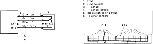
Suzuki Samurai TP Sensor (TPS) Wiring Diagram - ECM Pins A18/B15, Wire Colors
Reference · 1986-1995 SamuraiAll 73 wiring diagrams
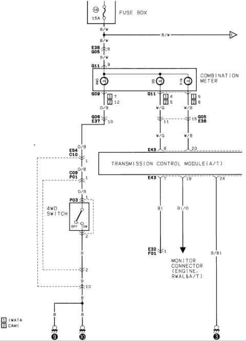
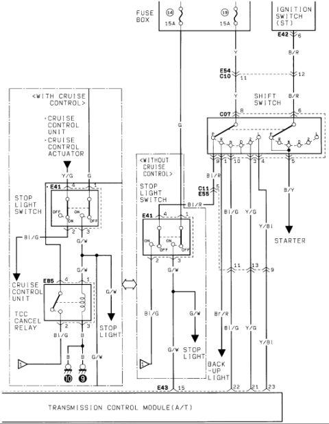
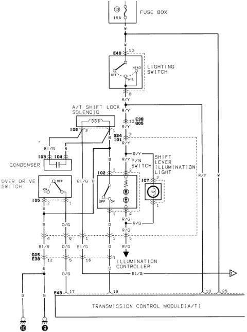
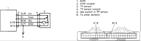
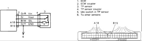
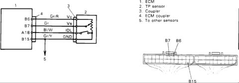
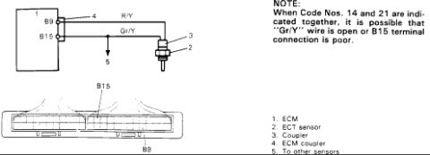
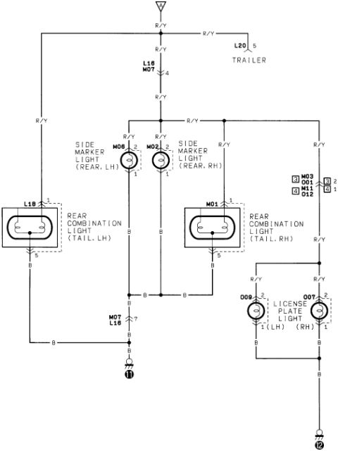
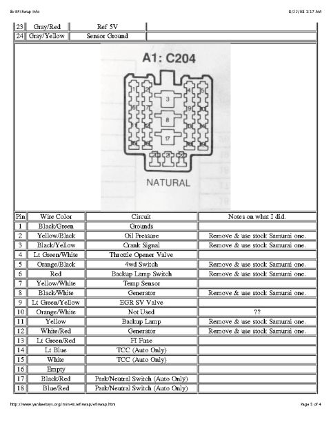
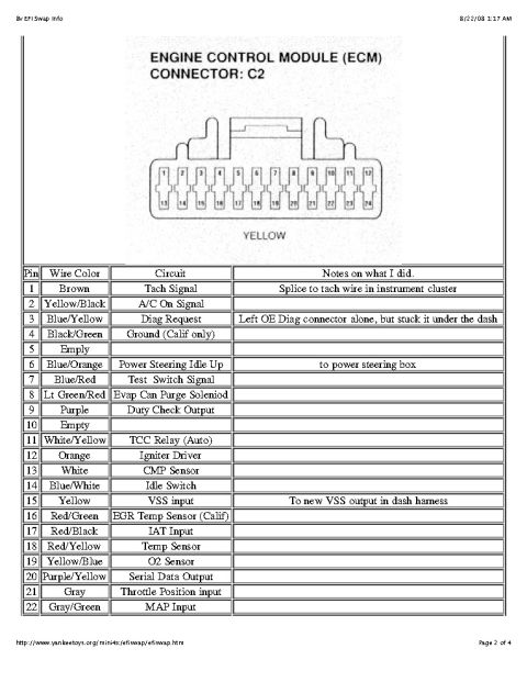
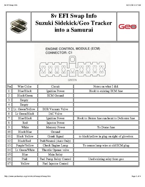
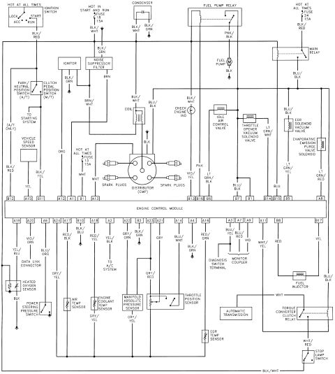
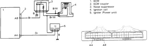

Wiring diagram showing the ECM-to-throttle-position-sensor circuit with idle switch and a coupler terminal layout.
Part of 1986-1995 Suzuki Samurai Wiring Diagrams
This document is a wiring diagram for the throttle position (TP) sensor circuit, uploaded to a 1986 Suzuki Samurai gallery. It shows the electrical connection between the ECM (item 1), its coupler (item 2), and the TP sensor (item 3) via the TP sensor coupler (item 4). Four wires connect the ECM to the sensor: Gr/R carrying Vin (sensor reference voltage), Gr carrying Vout (sensor output signal), Bl/W carrying IDL (the idle switch signal, from ECM pin A18), and Gr/Y as GND (ground, ECM pin B15), which also continues on "to other sensors" (item 6). The TP sensor contains an integrated idle switch (item 5), drawn as a switch contact inside the sensor. A connector face illustration of the ECM coupler identifies the physical terminal positions of pins A18 and B15 within the multi-pin connector, useful for probing or back-testing the circuit. A reader can learn the wire colors, signal names, ECM pin assignments, and connector pin locations needed to diagnose TP sensor and idle switch circuit problems.
Is this accurate? Sign in to help verify it.
Frequently asked questions
- What wire colors are used for the Suzuki TP sensor circuit?
- Gr/R for Vin, Gr for Vout, Bl/W for IDL, and Gr/Y for GND.
- Which ECM pins connect to the TP sensor idle switch and ground?
- Pin A18 carries the IDL signal (Bl/W wire) and pin B15 is GND (Gr/Y wire).
- Does the TP sensor include an idle switch?
- Yes, the diagram shows an idle switch (item 5) built into the TP sensor (item 3).
- Is the TP sensor ground shared with other components?
- Yes, the Gr/Y GND wire is shown continuing 'to other sensors' (item 6).
- What components are labeled in the diagram?
- 1. ECM, 2. ECM coupler, 3. TP sensor, 4. TP sensor coupler, 5. Idle switch in TP sensor, 6. To other sensors.

No comments yet.