Home/
Registry/
Suzuki/
Samurai/
1986-1995/
“Little Blue”/
Photo
supermotors.net/registry/media/420702
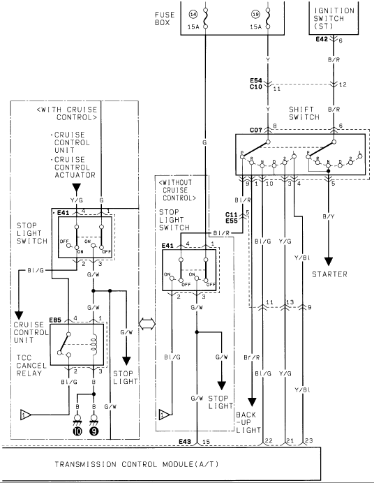
Suzuki Automatic Transmission Control Module Wiring Diagram - Shift Switch & TCM
Reference · 1986-1995 SamuraiAll 73 wiring diagrams
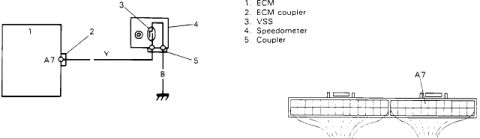
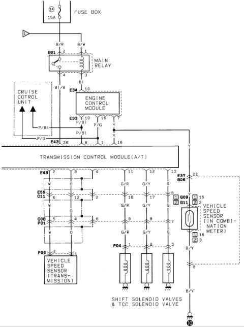
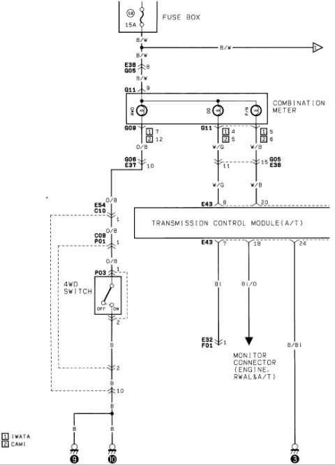
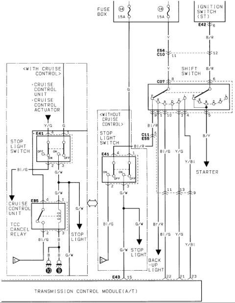
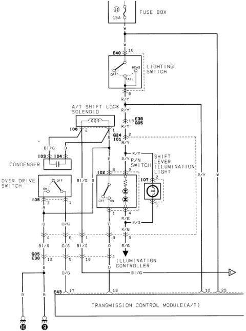
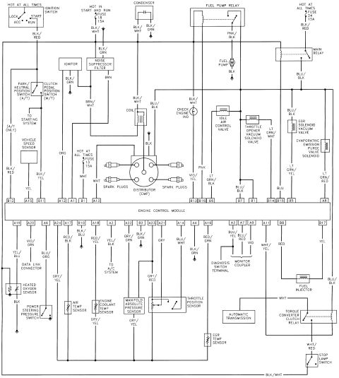
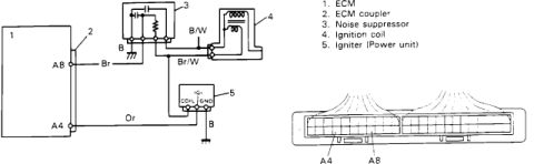
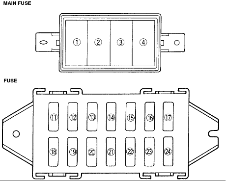

Wiring diagram of the stop light, cruise control and back-up light circuits tied to the shift switch and transmission control module.
Part of 1986-1995 Suzuki Samurai Wiring Diagrams
This document is one page of a Suzuki automatic transmission wiring diagram (uploaded as "tranny2.gif") showing the circuits feeding the Transmission Control Module (A/T) at connector E43 (pins 15, 22, 21, 23). Power comes from fuse box positions 14 and 15A and 19 (15A), plus the ignition switch (ST) terminal via connector E42 pin 6 (B/R wire). The diagram covers the shift switch (connector C07), which routes to the starter (B/Y wire) and the back-up light (Br/R wire), and carries Bl/G, Y/G, and Y/Bl signal wires to the TCM. Two stop light switch variants are shown: one <WITH CRUISE CONTROL> (connector E41 with the cruise control unit, cruise control actuator, and E85 TCC cancel relay, grounded at points 10 and 9) and one <WITHOUT CRUISE CONTROL> (connectors C11/E55 and E41). Both variants send a G/W wire to the stop light and a Bl/G signal onward. Intermediate connectors E54/C10 (pins 11, 12) and pins 11, 13, 9 are identified. Wire colors throughout include G, Y, B/R, Y/G, Bl/G, G/W, Bl/R, B/Y, Br/R, Y/Bl, and B (ground). A reader can trace TCM inputs, stop light switch wiring differences by cruise control equipment, and shift switch outputs to the starter and back-up lights.
Is this accurate? Sign in to help verify it.
Frequently asked questions
- What fuses power the transmission control circuit in this diagram?
- Fuse box positions 14 and 19, each rated 15A, along with a B/R feed from the ignition switch (ST) terminal via connector E42 pin 6.
- Which connector and pins go to the Transmission Control Module?
- Connector E43, with pins 15, 22, 21, and 23 shown entering the Transmission Control Module (A/T).
- How does the stop light switch wiring differ with and without cruise control?
- With cruise control, the stop light switch (E41) works with the cruise control unit, cruise control actuator, and an E85 TCC cancel relay grounded at points 10 and 9. Without cruise control, the stop light switch (E41, via C11/E55 on a Bl/R wire) feeds the stop light directly on a G/W wire and sends a Bl/G signal onward.
- What wire color goes to the starter from the shift switch?
- A B/Y (black/yellow) wire from the shift switch (connector C07) goes to the starter.
- What wire color feeds the back-up light?
- A Br/R (brown/red) wire from the shift switch circuit feeds the back-up light.

No comments yet.