Home/
Registry/
Suzuki/
Samurai/
1986-1995/
“Little Blue”/
Photo
supermotors.net/registry/media/420697
Suzuki Samurai ECT Sensor Wiring Diagram - ECM Terminals B9/B15, Codes 14 & 21
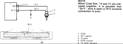
Wiring diagram showing the ECM-to-ECT-sensor circuit with R/Y and Gr/Y wires and a coupler terminal layout.
This document is a wiring diagram for the Engine Coolant Temperature (ECT) sensor circuit, uploaded as part of a 1986 Suzuki Samurai reference album. It shows the ECT sensor (item 2) connected through a coupler (item 3) to the ECM (item 1) via the ECM coupler (item 4). Two wires are identified: an "R/Y" (red/yellow) wire connecting to ECM terminal B9, and a "Gr/Y" (gray/yellow) wire connecting to ECM terminal B15. A branch labeled item 5 indicates the circuit also goes "to other sensors." A pinout illustration of the ECM coupler shows the physical locations of terminals B15 and B9. A diagnostic note explains that when trouble Code Nos. 14 and 21 are indicated together, it is possible that the "Gr/Y" wire is open or the B15 terminal connection is poor. Readers can use this diagram to trace the ECT sensor circuit, identify wire colors and ECM terminal positions, and troubleshoot combined codes 14 and 21.
Is this accurate? Sign in to help verify it.
Frequently asked questions
- What ECM terminals does the ECT sensor connect to?
- The ECT sensor connects to ECM terminal B9 via the R/Y wire and terminal B15 via the Gr/Y wire.
- What does it mean when Codes 14 and 21 appear together?
- Per the note, when Code Nos. 14 and 21 are indicated together, it is possible that the "Gr/Y" wire is open or the B15 terminal connection is poor.
- What wire colors are used in the ECT sensor circuit?
- R/Y (to terminal B9) and Gr/Y (to terminal B15).
- What components are shown in the diagram?
- 1. ECM, 2. ECT sensor, 3. Coupler, 4. ECM coupler, and 5. a branch going to other sensors.
Comments
More from this build














No comments yet.