Home/
Registry/
Suzuki/
Samurai/
1986-1995/
“Little Blue”/
Photo
supermotors.net/registry/media/420696
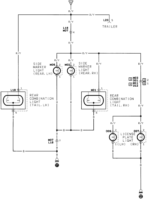
Suzuki Samurai Tail Lamp Wiring Diagram - Side Marker & License Plate Lights
Reference · 1986-1995 SamuraiAll 73 wiring diagrams
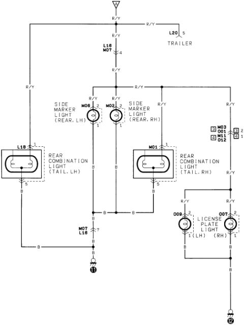
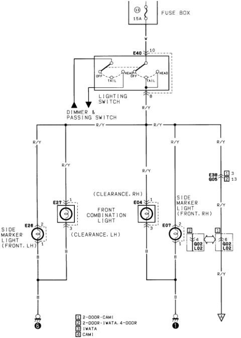
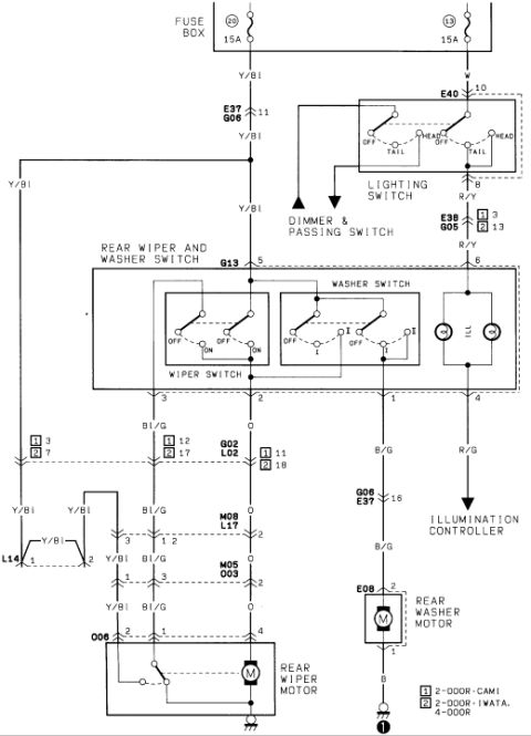
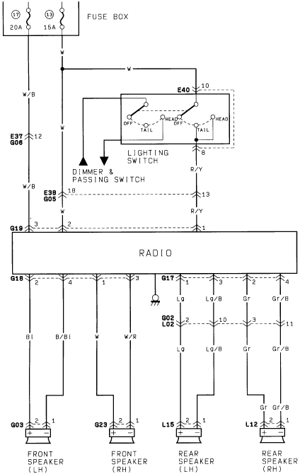
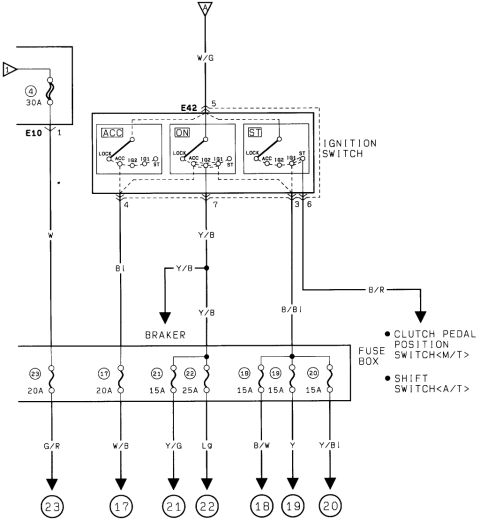
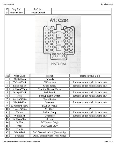
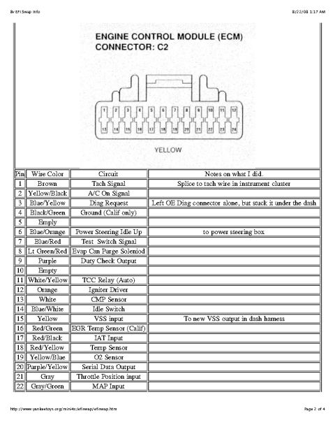
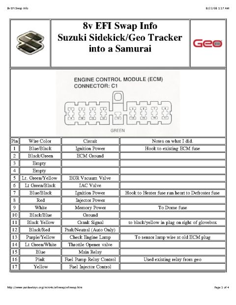
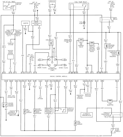
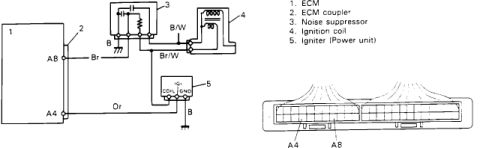

Wiring diagram of the rear lighting circuit including rear combination, side marker, license plate lights and trailer connector.
Part of 1986-1995 Suzuki Samurai Wiring Diagrams
This is a scanned automotive wiring diagram showing the tail lamp (rear lighting) circuit. Power arrives on a Red/Yellow (R/Y) wire from a connector at the top, with a branch to connector L20 pin 5 for the TRAILER circuit. The R/Y feed passes through connector L16/M07 (pin 4) and distributes to: the rear side marker lights, LH (bulb M06) and RH (bulb M02); the rear combination tail lights, LH (L18, pin 1 in, pin 5 out) and RH (M01, pin 1 in, pin 5 out); and the license plate lights, LH (O09) and RH (O07). All lamp returns are Black (B) wires. The left/center lamps' grounds collect through connector M07/L16 pin 7 to ground point 11, while the license plate lights ground at point 12. A small connector legend box lists M03, O01, M11, and O12 with pin counts 8, 2, 4, 4. A reader can learn wire colors (R/Y feed, B ground), connector identifiers and pin numbers, and how the tail, side marker, license plate, and trailer lighting circuits interconnect on this vehicle.
Is this accurate? Sign in to help verify it.
Frequently asked questions
- What wire color feeds the tail lights in this diagram?
- A Red/Yellow (R/Y) wire supplies power to the rear combination lights, side marker lights, license plate lights, and the trailer connector; Black (B) wires provide ground.
- Which connector feeds the trailer lighting circuit?
- Connector L20, pin 5, taps off the R/Y tail light feed for the TRAILER circuit.
- What are the connector/bulb IDs for the rear side marker lights?
- M06 is the rear LH side marker light and M02 is the rear RH side marker light, each fed on pin 2 (R/Y) and grounded on pin 1 (B).
- How are the license plate lights identified and grounded?
- O09 (LH) and O07 (RH) license plate lights receive R/Y power on pin 2, and their B ground wires join and run to ground point 12.
- Where do the tail and side marker light grounds terminate?
- Their Black (B) wires join and pass through connector M07/L16 pin 7 to ground point 11.

No comments yet.