SuperMotors SuperMotors SUPERMOTORS Search: try “orange Bronco on 35s”
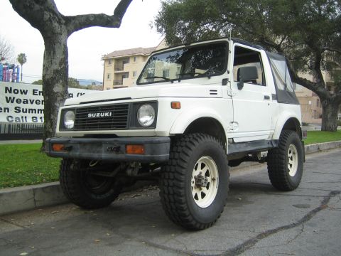
Home/ Registry/ Suzuki/ Samurai/ 1986-1995/ “Little Blue”/ Photo supermotors.net/registry/media/420699

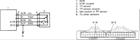
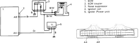
Suzuki Samurai TP Sensor (TPS) Wiring Diagram - ECM Pins A18 & B15, Wire Colors
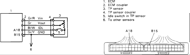
ECM and TP sensor wiring diagram with Vin, Vout, IDL, GND lines and coupler pinout
ECM and TP sensor wiring diagram with Vin, Vout, IDL, GND lines and coupler pinoutOriginal file
ECM and TP sensor wiring diagram with Vin, Vout, IDL, GND lines and coupler pinout

Reference · 1986-1995 SamuraiAll 73 wiring diagrams
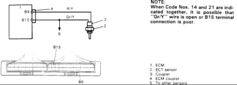
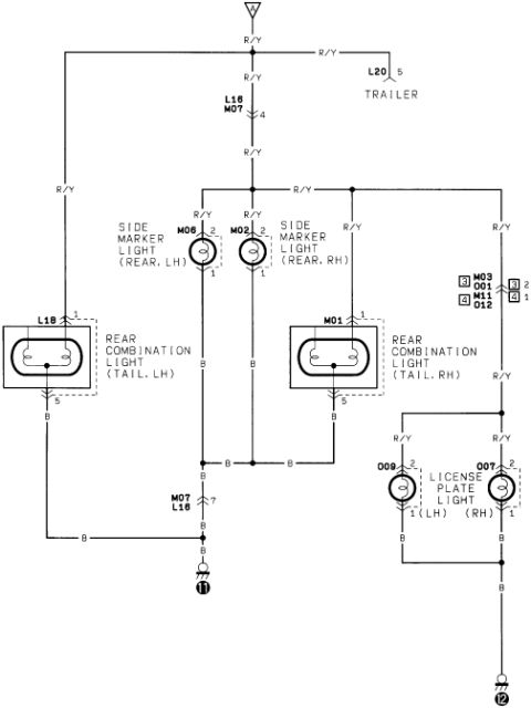
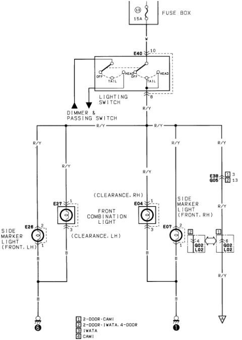
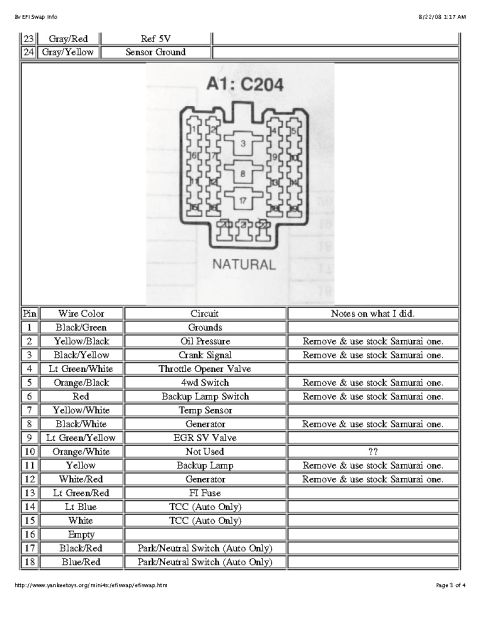
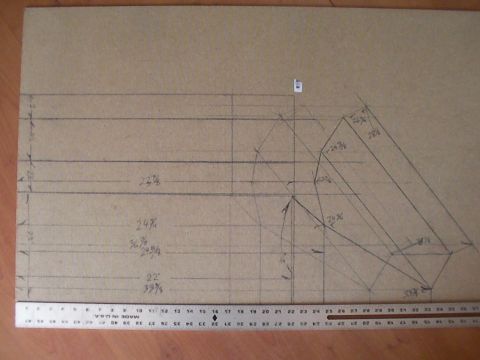
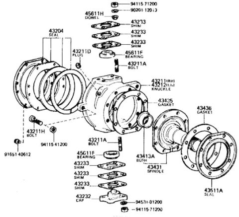
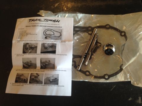
Suzuki Automatic Transmission Control Module Wiring Diagram - Shift Switch & TCM Suzuki A/T Shift Lock & Overdrive Switch Wiring Diagram - TCM Circuit Suzuki Samurai TP Sensor (TPS) Wiring Diagram - ECM Pins A18/B15, Wire Colors Suzuki Samurai TP Sensor (TPS) Wiring Diagram - ECM Pins A18 & B15, Wire Colors Suzuki Samurai TP Sensor (TPS) Wiring Diagram - ECM Pins B6, B7, A18, B15 Suzuki Samurai ECT Sensor Wiring Diagram - ECM Terminals B9/B15, Codes 14 & 21 Suzuki Samurai Tail Lamp Wiring Diagram - Side Marker & License Plate Lights Suzuki Clearance & Side Marker Lamp Wiring Diagram - Fuse 13 15A, E40 Switch Connector A1: C204 pinout with wire color, circuit and swap notes for pins 1-18 Suzuki Samurai 8v EFI Swap ECM Connector C2 Pinout - Wire Colors & Circuits Suzuki Sidekick/Geo Tracker 8v EFI Swap into Samurai - ECM C1 Pinout & Wiring Engine control module wiring diagram with main relay, fuel pump relay, heated oxygen sensor and IAC valve 73wiring diagrams1986-1995 Suzuki Samurai More reference Suzuki Samurai Igniter & Ignition Coil Wiring Schematic - ECM Pins A4/A8Schematic 1986 Suzuki Samurai Fuse Box Diagram - Main Fuse Block & Fuse Panel LayoutFuse chart 6th annual Pine Barrens Cleanup flyer for Wharton State Forest, October 28, 2007Brochure Suzuki Samurai 8v EFI Swap Wiring - Pin Colors & 8A-20 Diagram Index (Pg 4)Manual page Suzuki Samurai Mitsubishi 12V Starter Data Plate - M3T41781 / 31100-83030Spec plate EGR and canister purge vacuum routing diagram with 13-item numbered component legendVacuum routing 1987 Suzuki Samurai Fabrication Template - Hand-Drawn Full-Size Layout w/ DimsBlueprint Photo of Purple Compact Car Front Wheel & Fender (Misfiled Samurai Doc Scan)Exploded parts Trail Tough Samurai Twisted T/T shift shaft installation instructions beside bagged shift shafts and gasketService procedure

Wiring diagram showing the ECM-to-throttle-position-sensor circuit with idle switch and a coupler terminal layout.

Part of 1986-1995 Suzuki Samurai Wiring Diagrams

AI caption · Photo 66 of 86

This document is a wiring diagram for the throttle position (TP) sensor circuit, uploaded as part of a 1986 Suzuki Samurai reference album. It shows the ECM (item 1) connecting through the ECM coupler (item 2) to the TP sensor coupler (item 4) and TP sensor (item 3). Four wires run between the ECM and TP sensor: Gr/R carrying Vin, Gr carrying Vout, Bl/W carrying IDL, and Gr/Y carrying GND. The diagram identifies ECM coupler pin A18 as the IDL (Bl/W) terminal and pin B15 as the ground (Gr/Y) terminal. Item 5 shows the idle switch built into the TP sensor on the IDL circuit, and an arrow (item 6) indicates that the ground wire also runs to other sensors. On the right, a drawing of the ECM coupler connector face shows the physical locations of pins A18 and B15 within the multi-pin connector. A reader can learn the wire colors, signal names, ECM pin assignments, and connector pin locations needed to test or troubleshoot the TP sensor and its integrated idle switch. The document itself contains no year, model, or part number information.

Is this accurate? Sign in to help verify it.

Frequently asked questions

What wire colors are used for the TP sensor circuit?
Gr/R for Vin, Gr for Vout, Bl/W for IDL, and Gr/Y for GND.
Which ECM coupler pins connect to the TP sensor?
Pin A18 is the IDL signal (Bl/W wire) and pin B15 is the ground (Gr/Y wire), as shown on the ECM coupler illustration.
Where is the idle switch located in this circuit?
The idle switch (item 5) is inside the TP sensor (item 3) and is connected on the IDL (Bl/W) circuit.
Does the TP sensor share any wiring with other components?
Yes, the Gr/Y ground wire has an arrow (item 6) labeled 'To other sensors', indicating it also grounds other sensors.

Comments

No comments yet.

More 1986-1995 Samurais