Home/
Registry/
Suzuki/
Samurai/
1986-1995/
“Little Blue”/
Photo
supermotors.net/registry/media/420705
Suzuki Samurai VSS Wiring Diagram - Vehicle Speed Sensor to ECM Pin A7

Reference · 1986-1995 SamuraiAll 73 wiring diagrams
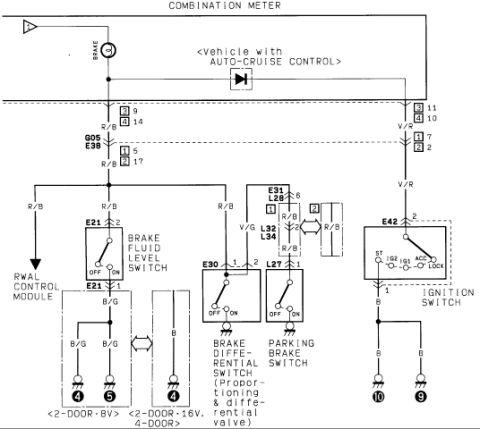
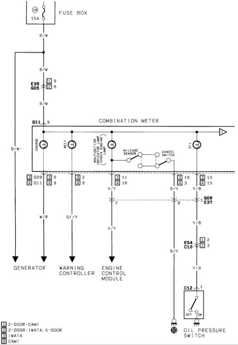
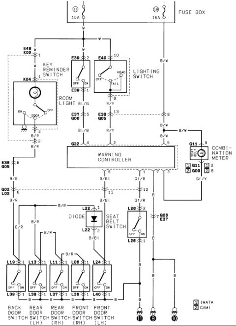
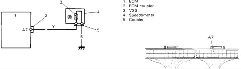
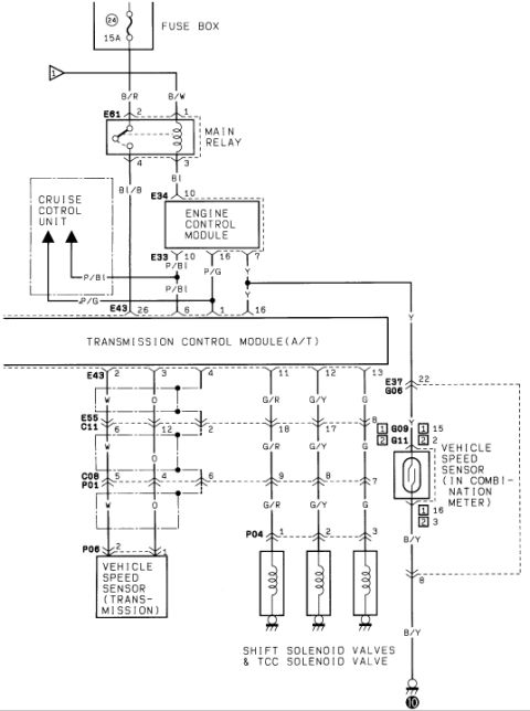
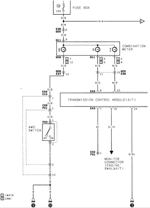
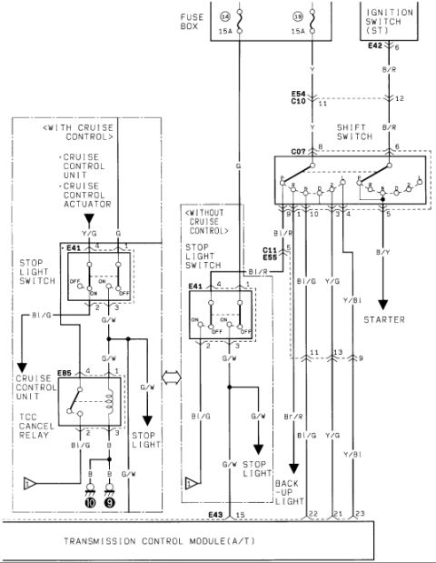
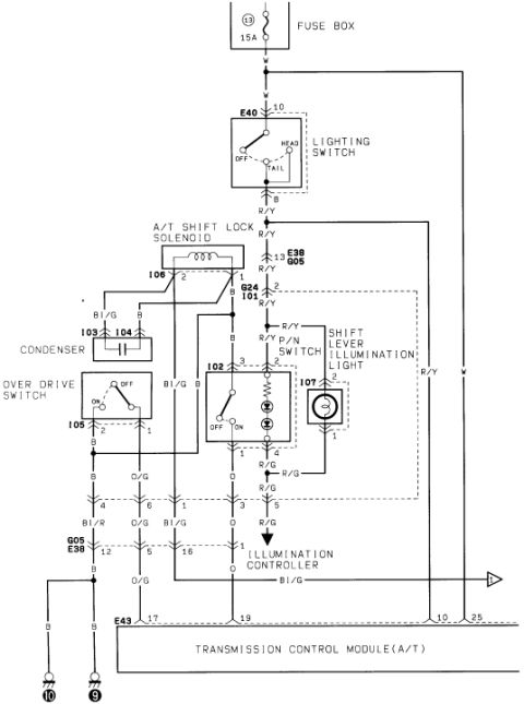
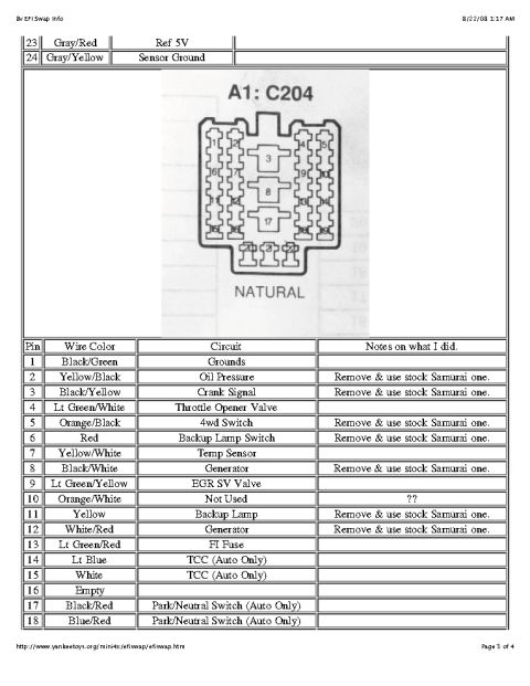
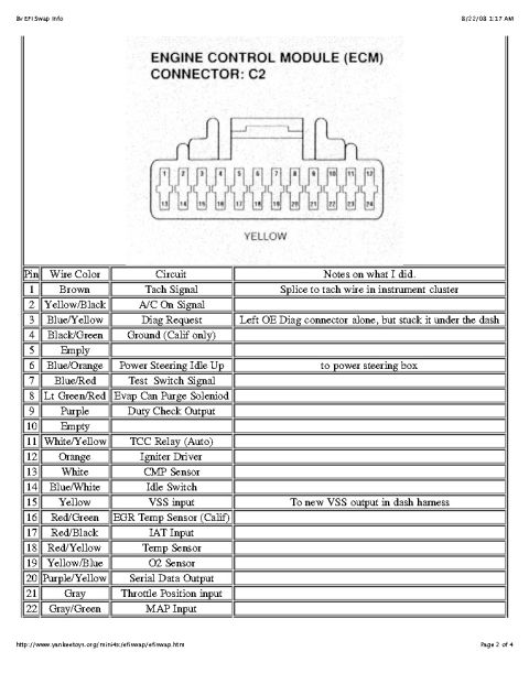
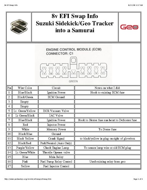
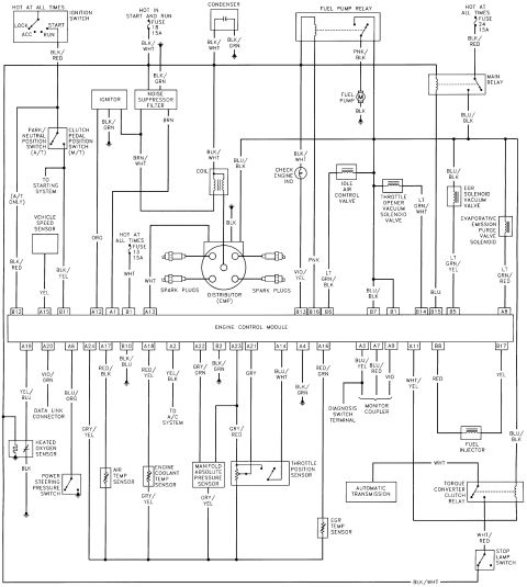
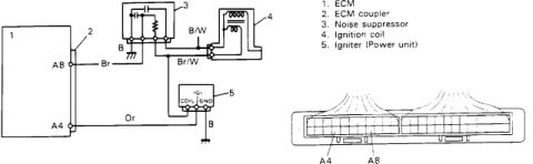

Wiring diagram showing the ECM-to-VSS circuit through the speedometer with a coupler terminal layout.
Part of 1986-1995 Suzuki Samurai Wiring Diagrams
This document is a simple wiring diagram for the Vehicle Speed Sensor (VSS) circuit, uploaded to the gallery of a 1986 Suzuki Samurai. The diagram shows the ECM (item 1) connecting through the ECM coupler (item 2) at terminal A7. A yellow (Y) wire runs from ECM terminal A7 to a coupler (item 5) at the speedometer (item 4), which houses the VSS (item 3). A black (B) wire from the coupler goes to chassis ground. A legend identifies the five numbered components: ECM, ECM coupler, VSS, speedometer, and coupler. Below the schematic is a connector face view of the ECM couplers, with the location of terminal A7 marked on the right-hand connector block, allowing a technician to locate the correct pin when testing the VSS signal circuit. From this document, a reader can learn the wire colors used in the VSS circuit (Y for signal, B for ground), the ECM pin (A7) that receives the vehicle speed signal, and that the VSS is integrated into the speedometer assembly. The document itself carries no year, model, or part-number information; it is one page of a larger set of circuit diagrams uploaded to the same album.
Is this accurate? Sign in to help verify it.
Frequently asked questions
- Which ECM terminal does the vehicle speed sensor signal connect to?
- The VSS/speedometer circuit connects to ECM terminal A7, shown both in the schematic and in the ECM connector face view.
- What wire color carries the VSS signal to the ECM?
- A yellow (Y) wire runs from the speedometer coupler to ECM terminal A7.
- Where is the VSS located according to this diagram?
- The VSS (item 3) is shown inside the speedometer assembly (item 4).
- How is the VSS circuit grounded?
- A black (B) wire from the coupler at the speedometer goes to chassis ground.
- What components are identified in the diagram legend?
- 1. ECM, 2. ECM coupler, 3. VSS, 4. Speedometer, 5. Coupler.






No comments yet.