Home/
Registry/
Ford/
Bronco/
1987-1991/
1987 Ford Bronco/
Photo
supermotors.net/registry/media/437893
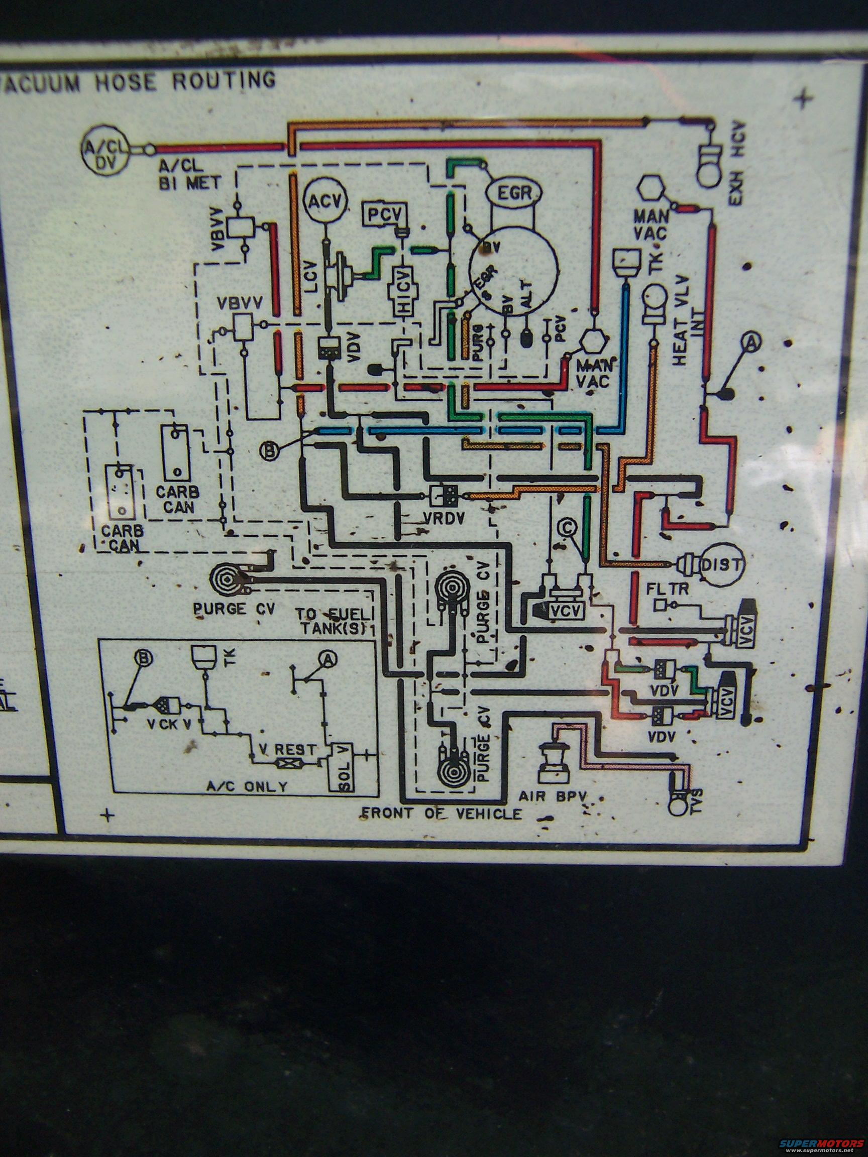
Ford Bronco Vacuum Hose Routing Diagram - Underhood Emissions Decal
Reference · 1987-1991 BroncoAll 12 vacuum routing diagrams
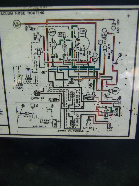



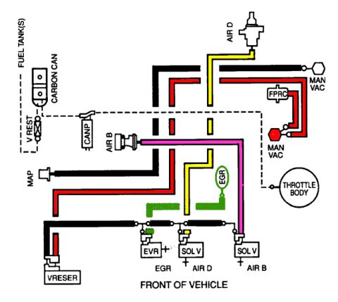
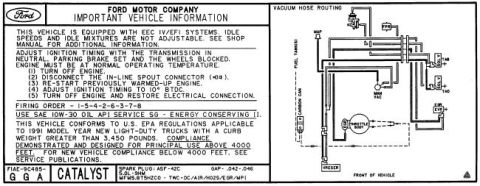

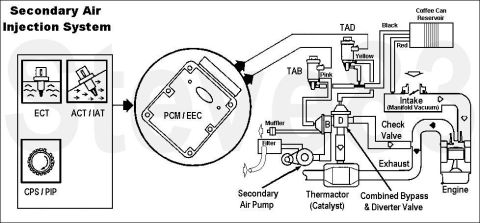
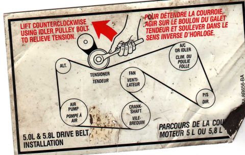










Vacuum hose routing diagram label showing color-coded hoses connecting the EGR, PCV, carbon canister, and air cleaner vacuum components.
Part of 1987-1991 Ford Bronco Vacuum Routing Diagrams
This document is a photograph of a factory underhood emissions decal titled "VACUUM HOSE ROUTING," uploaded to a 1987 Ford Bronco gallery. It shows the complete vacuum hose schematic for a carbureted engine, with color-coded hoses (red, orange, green, blue, black, and dashed lines) connecting emissions and vacuum components. Labeled components include the air cleaner duct valve (A/CL DV) and bi-metal sensor (A/CL BI MET), ACV, PCV, LCV, HICV, EGR valve, a manifold vacuum tree with ports marked EGR, BV, ALT, PURG, and PCV, two VBVV valves, multiple VDV and VCV valves, VRDV, two carbon canisters (CARB CAN), multiple purge control valves (PURGE CV) with a line marked "TO FUEL TANK(S)," heat valve (HEAT VLV INT), exhaust heat control valve (EXH HCV), distributor (DIST), filter (FLTR), air bypass valve (AIR BPV), and TVS. Circled callouts A, B, and C mark connection points, including to a lower-left inset diagram labeled "A/C ONLY" showing a vacuum check valve (V CK V), vacuum restrictor (V REST), solenoid valve (SOL V), and tank (TK). A "FRONT OF VEHICLE" orientation arrow appears at bottom. The decal gives no year, engine, or calibration number in the visible portion.
Is this accurate? Sign in to help verify it.
Frequently asked questions
- What components are shown on this vacuum hose routing diagram?
- It shows the A/CL DV and A/CL BI MET on the air cleaner, ACV, PCV, LCV, HICV, EGR valve, a manifold vacuum tree (EGR, BV, ALT, PURG, PCV ports), VBVV, VDV, VCV, VRDV valves, carbon canisters (CARB CAN), purge control valves (PURGE CV), HEAT VLV INT, EXH HCV, distributor (DIST), filter (FLTR), AIR BPV, and TVS.
- Does the diagram show vacuum routing for air conditioning?
- Yes. A separate inset box labeled "A/C ONLY" shows a circuit with a tank (TK), vacuum check valve (V CK V), vacuum restrictor (V REST), and solenoid valve (SOL V), connected via callouts A and B to the main diagram.
- Where does the evaporative purge circuit connect according to this decal?
- The purge control valves (PURGE CV) connect to the carbon canisters (CARB CAN) and to a line marked "TO FUEL TANK(S) 1", indicating provision for one or more fuel tanks.
- What do the circled letters A, B, and C mean on this diagram?
- They are connection callouts linking points in the main vacuum diagram; A and B also appear in the "A/C ONLY" inset, showing where the A/C vacuum circuit ties into the main routing.
- Does this decal identify the vehicle year or engine?
- No year, engine size, or calibration number is visible in this portion of the decal; it is titled only "VACUUM HOSE ROUTING" with a "FRONT OF VEHICLE" orientation marker.






No comments yet.