Ford Bronco Vacuum Hose Routing Diagram - Under-Hood Emissions Decal
Reference · 1987-1991 BroncoAll 12 vacuum routing diagrams


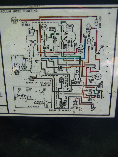


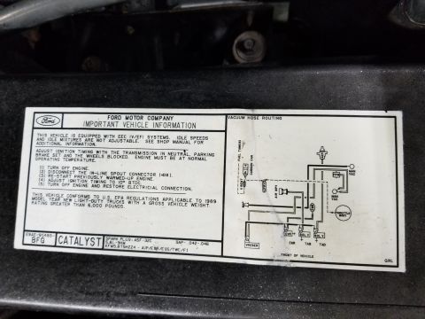
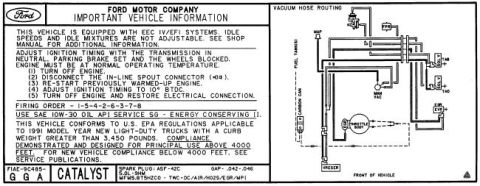











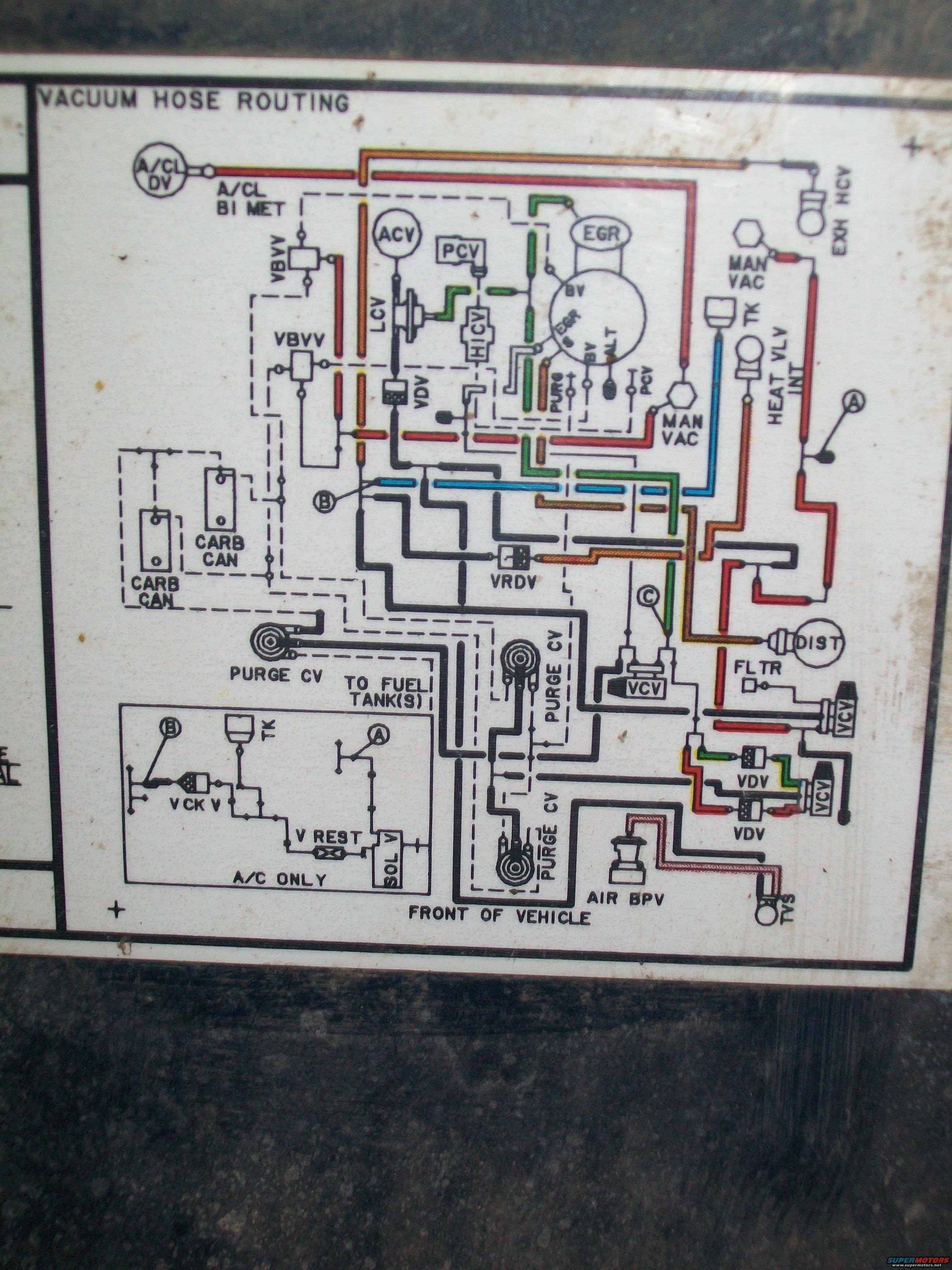
Color-coded underhood vacuum hose routing label showing connections to EGR, carb canister, VCV and distributor.
Part of 1987-1991 Ford Bronco Vacuum Routing Diagrams
This document is a photograph of a factory under-hood emissions decal titled "VACUUM HOSE ROUTING," uploaded to the gallery of a 1987 Ford Bronco. The decal shows a color-coded schematic of the engine's vacuum hose connections, with hoses drawn in red, orange, green, blue, yellow/brown, pink and black/dashed lines. Labeled components include the air cleaner delay valve (A/CL DV) and bi-metal sensor (A/CL BI MET), vacuum bias vent valves (VBVV), air control valve (ACV), PCV valve, EGR valve, load control valve (LCV), HICV, vacuum delay valves (VDV), exhaust heat control valve (EXH HCV), manifold vacuum taps (MAN VAC), heat valve internal (HEAT VLV INT), two carburetor charcoal canisters (CARB CAN), VRDV, multiple purge control valves (PURGE CV), vacuum control valves (VCV), the distributor (DIST), a filter (FLTR), air bypass valve (AIR BPV), and TVS. Connection points A, B, and C link sections of the diagram, and an inset labeled "A/C ONLY" shows a check valve (V CK V), vacuum restrictor (V REST), solenoid valve (SOL V), and tank (TK) circuit. A note indicates routing "TO FUEL TANK(S)," and the diagram is oriented with "FRONT OF VEHICLE" at the bottom. Useful for restoring correct vacuum line routing.
Is this accurate? Sign in to help verify it.
Frequently asked questions
- What does this under-hood decal show?
- It shows the factory vacuum hose routing diagram, with color-coded hoses connecting components such as the A/CL DV, EGR, PCV, ACV, VDV, VCV, PURGE CV, CARB CAN canisters, distributor (DIST), AIR BPV, and EXH HCV.
- Does the diagram cover A/C-equipped vehicles?
- Yes, there is an inset box labeled 'A/C ONLY' showing a circuit with TK, V CK V (check valve), V REST, and SOL V (solenoid valve) tied to connection points A and B.
- How is the diagram oriented?
- The bottom of the diagram is labeled 'FRONT OF VEHICLE,' so the layout is drawn relative to the front of the truck.
- Are there connections to the fuel system shown?
- Yes, a purge control valve (PURGE CV) line is labeled 'TO FUEL TANK(S),' and two carburetor canisters (CARB CAN) are shown on the left side.
- What ports are on the central multi-port vacuum fitting?
- The large circular multi-port fitting is labeled with ports for BV, EGR, BV, ALT, PURG, and PCV.






No comments yet.