Ford 5.0 AIR Injection (Thermactor) System Diagram - Pump, Hoses & Part Numbers

Reference · 1987-1991 BroncoAll 12 vacuum routing diagrams




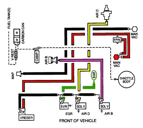
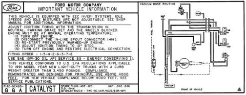

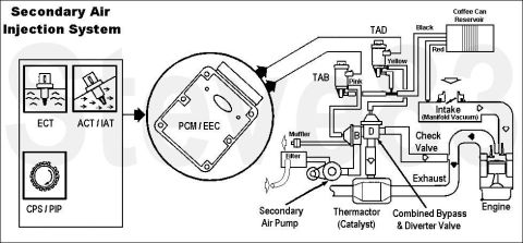
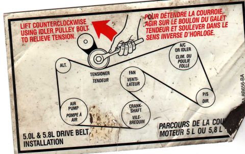
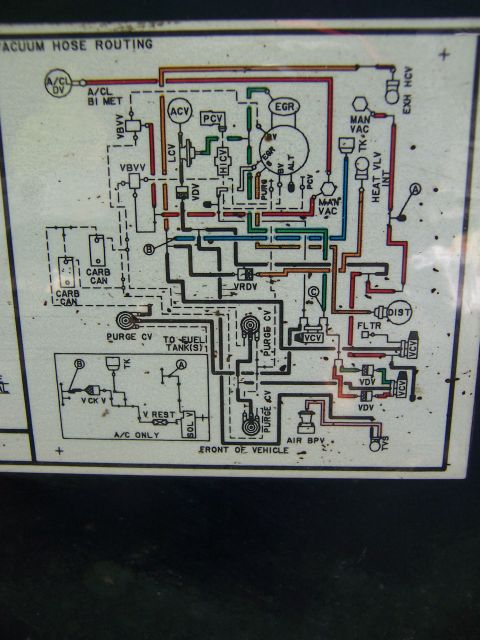












Vacuum and emissions hose routing diagram showing labeled hoses and fittings with Ford part numbers.
Part of 1987-1991 Ford Bronco Vacuum Routing Diagrams
This is a Ford exploded parts diagram (drawing number P-20661, printed/dated 09/26/2008) showing the AIR injection (Thermactor secondary air injection) system routing and components on a V8 engine. Two views are shown: an upper view of the engine's top/rear showing air hoses, check valves, and tubing (callouts 9F491, 9G424, 9G459, 9A487, 9B449, 9B466) with hose clamps (388497-S8), and a lower front view showing the air pump (9A486), pump pulley (9B447), silencer/filter (9H467, 9B458), air bypass/diverter valve (9B289), brackets and hoses (9F451, 9B450, 9K446, 9S449, 9F287, 9H308), tensioner/idler hardware (10A313, 6B209), and associated fasteners (56543-S36, 34976-S2, 57648-S, 56192-S, 390300-S2, 389483-S36, N802493-S2, 386951-S, 34656-S, 56124-S2). A reader can identify every Ford base part number and fastener spec for the AIR injection plumbing and pump assembly, along with hose routing between the pump, bypass valve, check valves, and exhaust manifolds. Uploaded as applying to a 1990 Ford Bronco 5.0L; the document itself states no year, model, or engine.
Is this accurate? Sign in to help verify it.
Frequently asked questions
- What is the Ford part number callout for the air injection pump in this diagram?
- The air pump is shown with base callout 9A486, with its pulley labeled 9B447 and attaching nut/hardware N802493-S2 (AU-9-P).
- What clamp part number is used on the AIR system hoses?
- Hose clamps throughout the diagram are labeled 388497-S8, used at multiple hose connections in both views.
- What fastener part numbers attach the brackets and valves?
- Visible fasteners include 56543-S36 (marked B-320-F and B-320-V), 34976-S2 (M-89-CD), 57648-S, 56192-S, 390300-S2, 389483-S36 (BB-187-EC), 386951-S, 34656-S, 56124-S2, and N802493-S2 (AU-9-P).
- What is the diagram/drawing number of this document?
- The drawing is identified as P-20661, with a date notation of 09/26/2008 in the lower right corner.
- Which callouts identify the air bypass valve and silencer components?
- Callout 9B289 marks the valve near the pump, 9H467 appears twice for the canister/silencer assembly and its bracket, and 9B458 labels the large hose to it.






No comments yet.