Ford 5.8L Secondary Air Injection (Thermactor) System Diagram - TAB/TAD Routing

Reference · 1987-1991 BroncoAll 12 vacuum routing diagrams


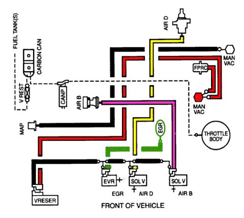
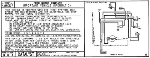
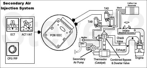















Diagram of the Ford Thermactor (secondary air injection) system: PCM/EEC controlling TAD and TAB vacuum solenoids, secondary air pump, combined bypass and diverter valve, with ECT/ACT/IAT/CPS/PIP sensor inputs.
Part of 1987-1991 Ford Bronco Vacuum Routing Diagrams
This document is a schematic diagram of the Secondary Air Injection (Thermactor) system as used on a Ford 5.8L engine, uploaded to a 1990 Ford Bronco gallery. It shows how the PCM/EEC computer receives inputs from the ECT (engine coolant temperature), ACT/IAT (air charge/intake air temperature), and CPS/PIP (crankshaft/profile ignition pickup) sensors, and in turn controls the TAB (Thermactor Air Bypass) and TAD (Thermactor Air Diverter) vacuum solenoids, identified by pink and yellow wires respectively. Vacuum is supplied from the intake manifold through a 'coffee can' vacuum reservoir with black and red vacuum lines. The belt-driven secondary air pump draws air through a filter and delivers it through the combined bypass & diverter valve (ports B and D), which can vent air to atmosphere through a small muffler, route it downstream to the Thermactor catalyst, or send it upstream through a check valve into the exhaust manifold near the engine. A reader can learn the overall vacuum routing, solenoid wire colors, air flow paths, and component relationships of the secondary air injection system, useful for diagnosing emissions faults, air pump plumbing, or TAB/TAD solenoid problems.
Is this accurate? Sign in to help verify it.
Frequently asked questions
- What sensors provide input to the PCM/EEC for the secondary air injection system?
- The diagram shows three inputs to the PCM/EEC: the ECT sensor, the ACT/IAT sensor, and the CPS/PIP sensor.
- What wire colors identify the TAB and TAD solenoids?
- The TAB solenoid is identified with a pink wire and the TAD solenoid with a yellow wire.
- Where does the secondary air injection system get its vacuum supply?
- Vacuum comes from the intake (manifold vacuum) and is stored in a 'coffee can' reservoir, connected with black and red vacuum lines.
- What does the combined bypass & diverter valve do?
- It receives air from the secondary air pump and directs it either to atmosphere (through a small muffler), downstream toward the Thermactor catalyst, or upstream through a check valve into the exhaust near the engine, via its B and D ports.
- What components are in the air pump's supply path?
- The secondary air pump draws air through a filter, and a small muffler is shown on the bypass vent of the valve.






No comments yet.