Home/
Registry/
Ford/
Bronco/
1987-1991/
1987 Ford Bronco/
Photo
supermotors.net/registry/media/1012788
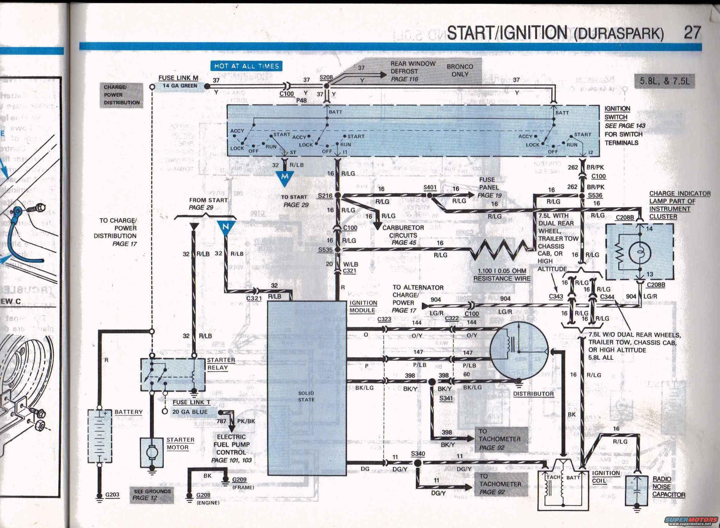
Ford Bronco/Truck Duraspark Start-Ignition Wiring Diagram 5.8L 7.5L - EVTM p.27
Reference · 1987-1991 BroncoAll 175 wiring diagrams



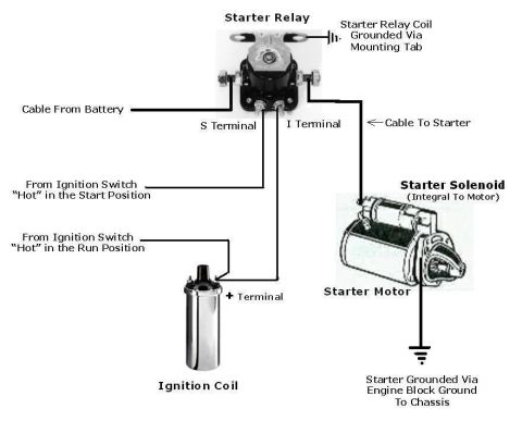
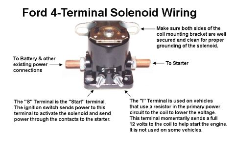

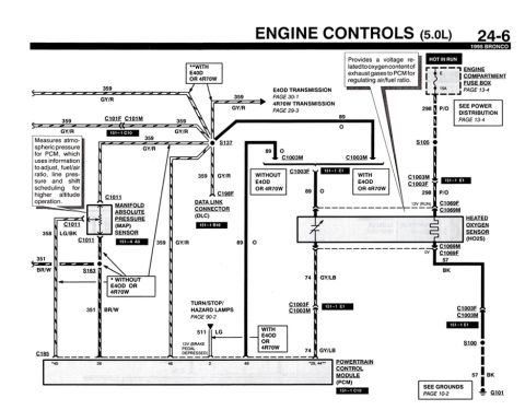

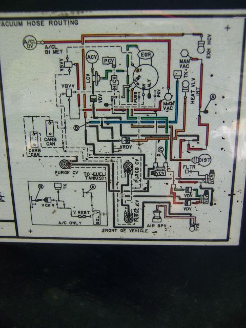








Ford start/ignition (Duraspark) wiring diagram page 27 covering 5.8L and 7.5L: ignition switch, starter relay/motor, 1.005-ohm resistance wire, fuse link, coil and charge circuits.
Part of 1987-1991 Ford Bronco Wiring Diagrams
This is page 27 of a Ford electrical and vacuum troubleshooting manual (EVTM), showing the Start/Ignition wiring diagram for Duraspark ignition on 5.8L and 7.5L engines. It traces power from Fuse Link M (14 GA green, circuit 37 yellow, hot at all times) through connector C100 and splice S208 to the ignition switch, with a Bronco-only branch to the rear window defrost (page 116). The switch feeds circuit 32 R/LB to the starter relay/starter motor circuit (M to start, page 29), circuit 16 R/LG to the fuse panel (page 19), carburetor circuits (page 45), and the Duraspark ignition module, and circuit 262 BR/PK to the charge indicator lamp in the instrument cluster. A 1.100 ± 0.05 ohm resistance wire is used on 7.5L trucks with dual rear wheels, trailer tow, chassis cab, or high altitude packages; other 7.5L and all 5.8L use the alternate 16 R/LG path through C343/C344. Module-to-distributor wiring (circuits 144 O/Y, 147 P/LB, 398 BK/Y, 11 DG/Y), ignition coil TACH/BATT terminals, tachometer feeds (page 92), fuse link T (20 GA blue) to electric fuel pump control (pages 101, 103), a radio noise capacitor, and grounds G203, G208 (engine), and G209 (frame) are all shown with wire gauges and color codes.
Is this accurate? Sign in to help verify it.
Frequently asked questions
- What wire feeds the Duraspark ignition switch battery terminal?
- Fuse link M, a 14 GA green fuse link on circuit 37 (yellow wire), which is hot at all times and passes through connector C100 and splice S208.
- What is the resistance wire value in this Duraspark ignition circuit?
- A 1.100 ± 0.05 ohm resistance wire, used on 7.5L engines with dual rear wheel, trailer tow, chassis cab, or high altitude applications.
- What wire colors run between the ignition module and the distributor?
- Circuit 144 orange/yellow (O/Y), circuit 147 purple/light blue (P/LB), and circuit 398 black/yellow (BK/Y), with circuit 60 BK/LG to the distributor ground side.
- Which circuit goes to the tachometer?
- Circuit 398 BK/Y and circuit 11 DG/Y both route to the tachometer, referenced to page 92.
- What powers the electric fuel pump control?
- Fuse link T (20 GA blue) from the starter relay feeds circuit 787 PK/BK to the electric fuel pump control, covered on pages 101 and 103.
- Does this diagram cover the Bronco rear window defrost feed?
- Yes: a Bronco-only branch of circuit 37 (yellow) from splice S208 feeds the rear window defrost, detailed on page 116.






No comments yet.