Home/
Registry/
Ford/
Crown Victoria/
1992-1997/
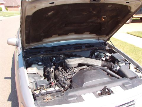
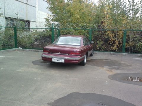
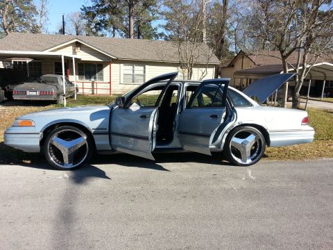
1992 Ford Crown Victoria/
Photo
supermotors.net/registry/media/484926
Ford C102 In-Line Connector Pinout Diagram (C102F/C102M) - Wire Colors

Connector pinout wiring diagram for the C102F and C102M in-line connectors listing pin numbers and wire color codes.
This document is a Ford wiring reference showing the pinout diagrams for in-line connector C102, presented as mating pair views: C102F (female side) and C102M (male side). Each connector face is drawn as a 16-cavity (4x4) connector with numbered pin positions. Around each connector face, the document lists the circuit number and wire color code assigned to each pin, such as 554 (Y/BK), 911 (W/LG), 205 (DB/LG), 16 (R/LG), 351 (BR/W), 224 (T/W), 67 (LG/Y) on one side, and 658 (PK/LG), 914 (T/O), 883 (PK/LB), 238 (DG/Y), 915 (PK/LB), 791 (R/PK), 676 (PK/O), 679 (GY/BK) on the other. Several circuits are marked with an asterisk *511 (LG), *787 (PK/BK or BK/PK), *359/*31 (GY/R and W/R), and *48, which the legend identifies as applying to Natural Gas Vehicle applications. A reader can use this diagram to identify which circuit number and wire color occupies each cavity of connector C102 when tracing wiring, diagnosing continuity across the connector, or repairing terminals. The document itself carries no year, model, or part number identification; it was uploaded to a 1992 Ford Crown Victoria gallery.
Is this accurate? Sign in to help verify it.
Frequently asked questions
- What connector does this diagram show?
- It shows the in-line connector C102, with both halves illustrated: C102F (female) and C102M (male), each a 16-cavity connector with numbered pins.
- What does the asterisk (*) next to some circuits mean?
- Per the legend, circuits marked with an asterisk (such as *511, *787, *359, *31, and *48) apply to Natural Gas Vehicle applications.
- What wire color is circuit 554 at connector C102?
- Circuit 554 is Y/BK (yellow/black) on both the C102F and C102M connector views.
- Which circuits pass through connector C102 according to this diagram?
- Circuits 554, 911, 511, 205, 16, 787, 351, 359, 31, 224, 67, 658, 914, 883, 238, 915, 48, 791, 676, and 679, each with its wire color code shown.
- How many pins does connector C102 have?
- The diagram shows 16 numbered pin cavities in each connector half (C102F and C102M).
Comments
More from this build



No comments yet.