Home/
Registry/
Ford/
Crown Victoria/
1992-1997/
1992 Ford Crown Victoria/
Photo
supermotors.net/registry/media/563609
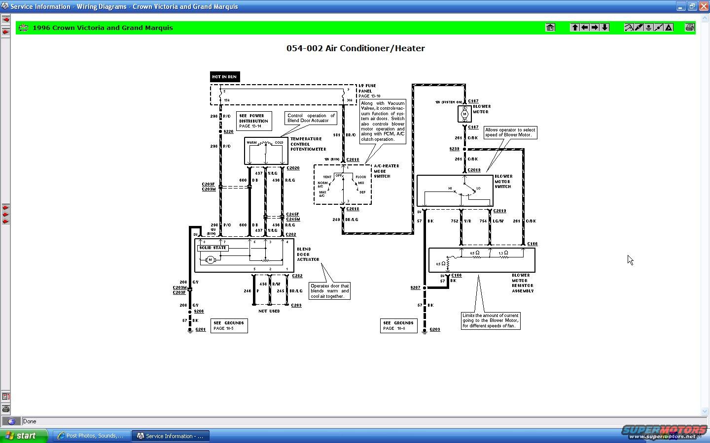
1996 Crown Victoria & Grand Marquis A/C Heater Wiring Diagram - Blower Motor
Reference · 1992-1997 Crown VictoriaAll 12 wiring diagrams
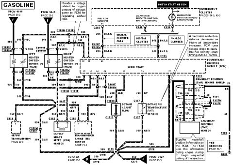
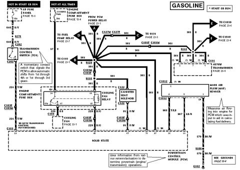
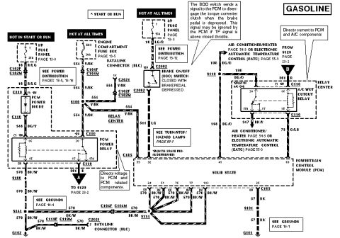
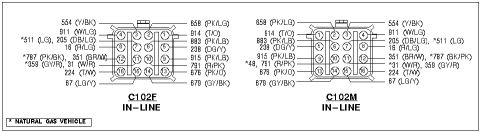
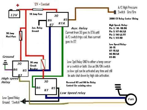
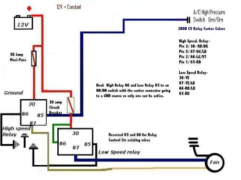
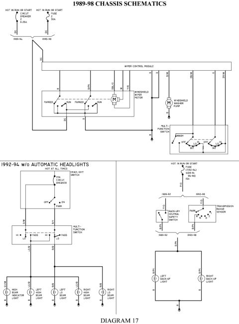
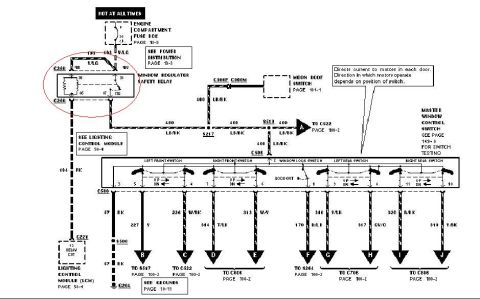
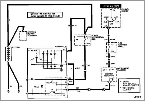
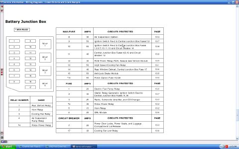
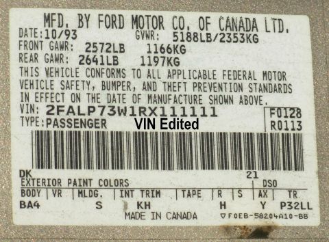

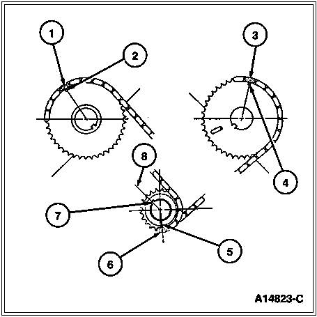
Service-software screenshot of the 1996 Crown Victoria/Grand Marquis A/C and heater wiring diagram (sheet 054-002).
Part of 1992-1997 Ford Crown Victoria Wiring Diagrams
This document is a screenshot of a factory-style wiring diagram, page 054-002 'Air Conditioner/Heater', from the 1996 Ford Crown Victoria and Mercury Grand Marquis service information. It shows the electrical circuits for the HVAC system, including power feeds from the instrument panel fuse panel (fuse 5, 15A and fuse 3, 30A, both hot in run), the temperature control potentiometer, the A/C-heater mode switch (VENT, OFF, NORM A/C, MAX A/C, FLOOR, MIX, DEF positions), the blend door actuator, the blower motor, the blower motor switch (HI/LO), and the blower motor resistor assembly (0.5 Ω, 1.3 Ω, 0.5 Ω resistors). Wire circuit numbers and colors are labeled throughout, such as 298 P/O, 181 BR/O, 600 DB, 437 V/LG, 436 R/LG, 243 DB/LG, 261 O/BK, 752 V/R, 754 LG/W, and 57 BK grounds to G201 and G203. Connectors (C167, C2018, C2019, C2020, C166, C282, C203F/M, C245F/M) and splices (S206, S207, S226, S239) are identified. Explanatory callouts describe component functions, e.g., the mode switch controls vacuum air doors, blower operation, and A/C clutch operation with the PCM, and the resistor assembly limits blower motor current for different fan speeds. Cross-references point to power distribution (page 13-14) and grounds (pages 10-5, 10-8).
This document covers 1996, which may differ from this 1992 Ford Crown Victoria.
Is this accurate? Sign in to help verify it.
Frequently asked questions
- What fuses power the A/C-heater system on the 1996 Crown Victoria/Grand Marquis?
- Two I/P fuse panel fuses (hot in run): fuse 5 (15A) feeds circuit 298 P/O to the blend door actuator side, and fuse 3 (30A) feeds circuit 181 BR/O to the A/C-heater mode switch. The fuse panel is referenced on page 13-10.
- What does the blower motor resistor assembly do?
- Per the diagram callout, it limits the amount of current going to the blower motor for different fan speeds. It contains resistors of 0.5 Ω, 1.3 Ω, and 0.5 Ω and connects through connector C166.
- What wire colors connect the blower motor switch to the resistor assembly?
- Circuit 752 V/R (violet/red) and circuit 754 LG/W (light green/white) run from the blower motor switch connector C2019 to the resistor assembly; circuit 261 O/BK carries blower motor feed and 57 BK is the ground.
- What positions does the A/C-heater mode switch have?
- VENT, OFF, NORM A/C, MAX A/C, FLOOR, MIX, and DEF. The callout notes the switch controls vacuum function of the system air doors, blower motor operation, and, with the PCM, A/C clutch operation.
- Where does the blend door actuator get ground?
- Through circuit 208 GY via connectors C203M/C203F to splice S206, then circuit 57 BK to ground G201 (see grounds page 10-5). The blower circuit grounds via 57 BK through S207 to G203 (page 10-8).





No comments yet.