Home/
Registry/
Ford/
Crown Victoria/
1992-1997/
1996 Ford Crown Victoria/
Photo
supermotors.net/registry/media/161999
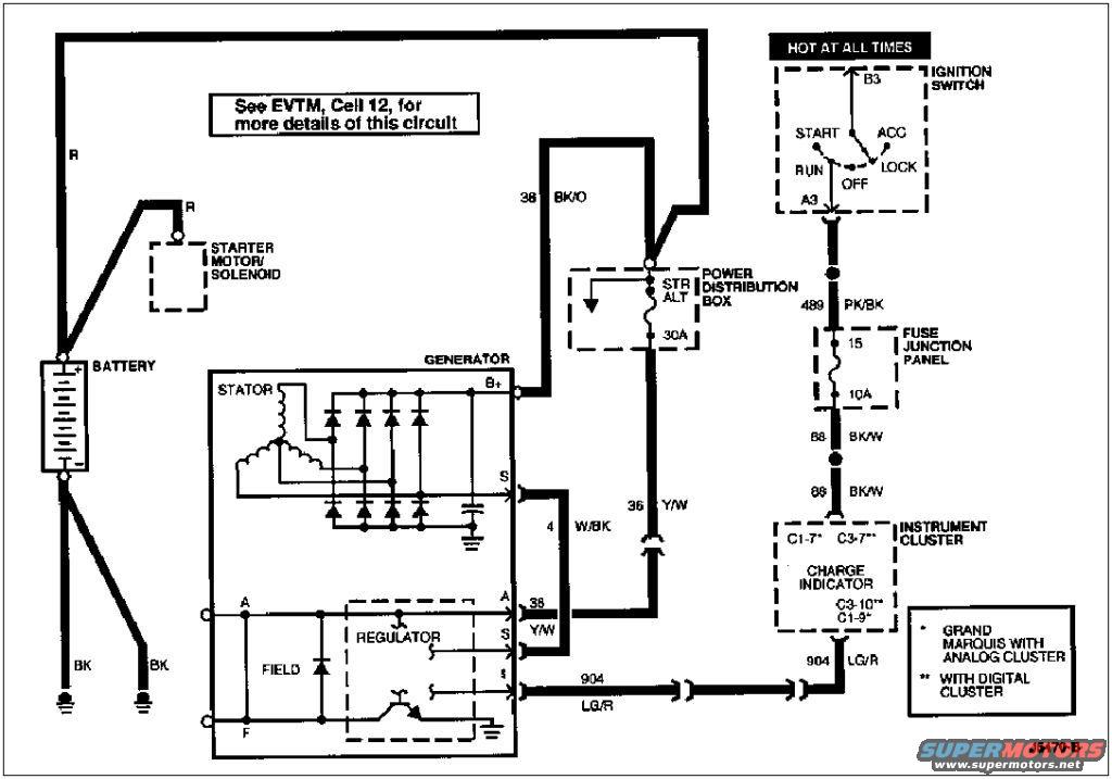
Ford Crown Victoria / Grand Marquis Charging System Wiring Diagram - Alternator
Reference · 1992-1997 Crown VictoriaAll 12 wiring diagrams
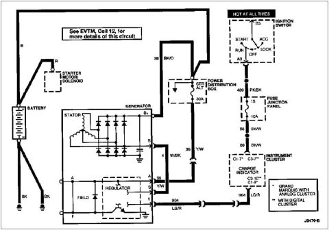
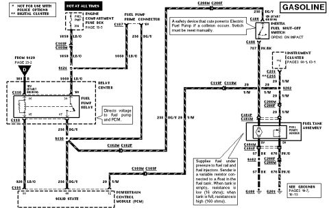
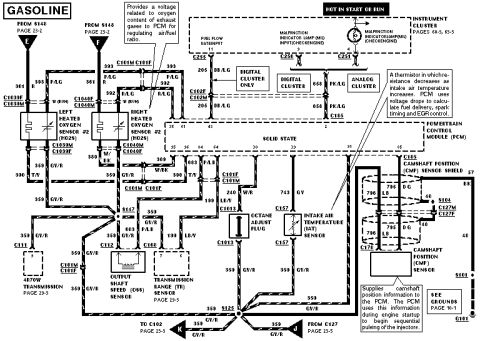
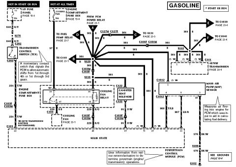
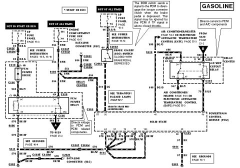
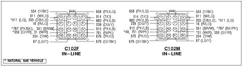
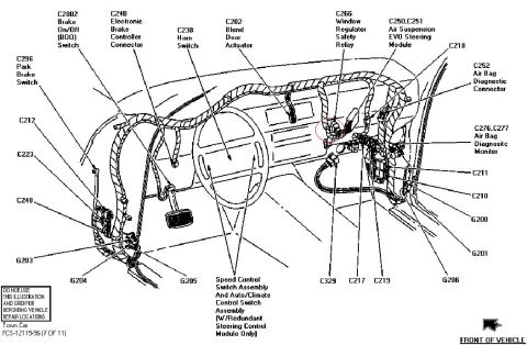


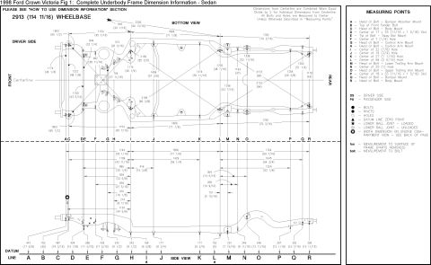
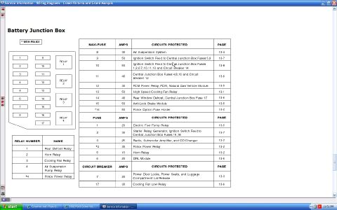
Charging system wiring diagram showing battery, generator/regulator, power distribution box and charge indicator with wire codes.
Part of 1992-1997 Ford Crown Victoria Wiring Diagrams
This document is a charging system (generator/alternator) wiring diagram, drawing number J5470-B, referencing EVTM Cell 12 for more circuit detail. It shows the battery connected via heavy R (red) cables to the starter motor/solenoid and to the generator B+ terminal through circuit 38 BK/O, which passes through a 30A fuse labeled STR ALT in the power distribution box. The generator internal detail includes the stator windings, rectifier diodes, and the internal regulator with A, S, I, and F terminals. Circuit 36 Y/W connects the S terminal path, circuit 4 W/BK connects the stator S output, and circuit 904 LG/R runs from the regulator I terminal to the charge indicator in the instrument cluster. Ignition switch power (hot at all times at terminal B3, output at A3 through RUN/START positions) feeds circuit 489 PK/BK to fuse 15 (10A) in the fuse junction panel, then continues as circuit 88 BK/W to the instrument cluster charge indicator. Cluster connector pins are noted as C1-7/C1-9 for Grand Marquis with analog cluster and C3-7/C3-10 with digital cluster. Readers can learn wire circuit numbers, colors, fuse ratings, and connector pinouts for diagnosing charging or charge-light problems.
Is this accurate? Sign in to help verify it.
Frequently asked questions
- What fuse protects the charge indicator circuit in the fuse junction panel?
- Fuse 15, rated 10A, fed by circuit 489 PK/BK from the ignition switch and feeding circuit 88 BK/W to the instrument cluster charge indicator.
- What size fuse is between the battery and the generator B+ output?
- A 30A fuse labeled STR ALT in the power distribution box, in the 38 BK/O circuit.
- What wire runs from the regulator I terminal to the charge indicator?
- Circuit 904 LG/R (light green/red) connects the regulator I terminal to the charge indicator in the instrument cluster.
- Which instrument cluster connector pins are used for the charge indicator?
- C1-7 and C1-9 on Grand Marquis with analog cluster; C3-7 and C3-10 with the digital cluster.
- Where can more details of this circuit be found?
- The diagram states: 'See EVTM, Cell 12, for more details of this circuit.'





No comments yet.