Home/
Registry/
Ford/
Crown Victoria/
1992-1997/
1992 Ford Crown Victoria/
Photo
supermotors.net/registry/media/484928
Ford PCM Power & MAF Sensor Wiring Diagram - Gasoline, 4R70W, Cooling Fan Relay
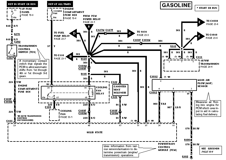
Wiring diagram showing PCM power relay, cooling fan relay, canister vent solenoid and mass air flow sensor circuits.
This document is one page of a Ford factory-style wiring diagram (EVTM format) covering the gasoline powertrain control system. It shows power distribution from the interior fuse panel (fuse 13, 15A, hot in start or run) and the engine compartment fuse box (60A cooling fan fuse, hot at all times) to the Powertrain Control Module (PCM) and related components. Circuits depicted include circuit 361 (red) PCM power feeds from the PCM power relay branching to the fuel pump relay, splices S129, S131, S148, S116, connectors C127, C101, C110, C111, C1039, C1040, the 4R70W transmission, canister vent solenoid (circuit 91 P/W), cooling fan relay (circuits 224 T/W and 229 R/O), cooling fan (228 DB), transmission control switch (640 R/Y), and mass air flow (MAF) sensor (circuits 968 T/LB, 967 LB/R, ground 570 BK/W to G102 via splice S106). PCM pin numbers (23, 40, 45, 67, 71, 37, 36, 88) and cross-references to other pages (13-6, 13-8, 23-1, 23-3, 23-6, 23-7, 29-4, 33-1, 10-4) are shown. Explanatory callouts describe the TCS momentary switch, MAF sensor function, and PCM operation.
Is this accurate? Sign in to help verify it.
Frequently asked questions
- What wire color and circuit feeds the PCM from the PCM power relay?
- Circuit 361, a red (R) wire, feeds from the PCM power relay and branches to the fuel pump relay, transmission, canister vent solenoid, MAF sensor and PCM pins 67 and 71.
- How is the mass air flow (MAF) sensor wired to the PCM?
- The MAF sensor connects through connector C1012: circuit 361 R for power, 968 T/LB to PCM pin 36, 967 LB/R to PCM pin 88, and ground through 570 BK/W to splice S106 and ground G102.
- What does the transmission control switch (TCS) do according to this diagram?
- It is a momentary contact switch that signals the PCM to allow automatic shifts from 1st through 4th or 1st through 3rd gears. It is fed by circuit 640 R/Y from fuse 13 (15A) in the I/P fuse panel.
- What fuse powers the cooling fan circuit?
- A 60A cooling fan fuse in the engine compartment fuse box (hot at all times) feeds circuit 37 Y to the cooling fan relay; the relay output 228 DB goes to the cooling fan (page 33-1).
- Which transmission does this diagram show connected to the PCM?
- The 4R70W transmission, via connector C111 with circuit 361 R feeds (details on page 29-4).
Comments
More from this build



No comments yet.