Home/
Registry/
Ford/
Crown Victoria/
1992-1997/
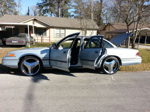
1994 Ford Crown Victoria/
Photo
supermotors.net/registry/media/822313
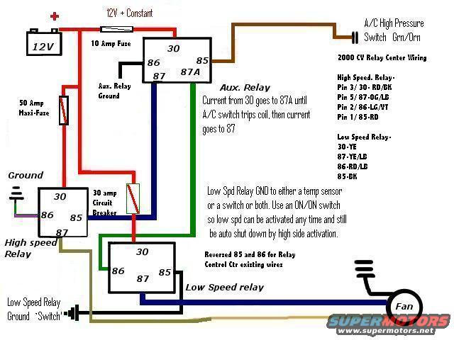
Ford Crown Victoria Electric Fan Relay Wiring Diagram - 2000 CV Relay Center
Reference · 1992-1997 Crown VictoriaAll 12 wiring diagrams
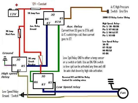
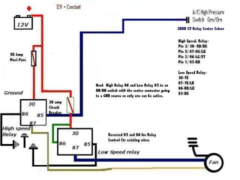
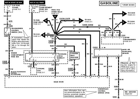
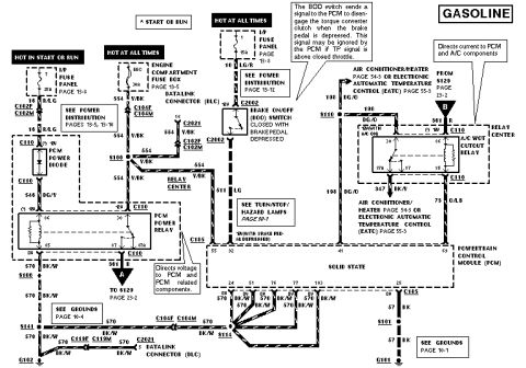
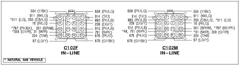
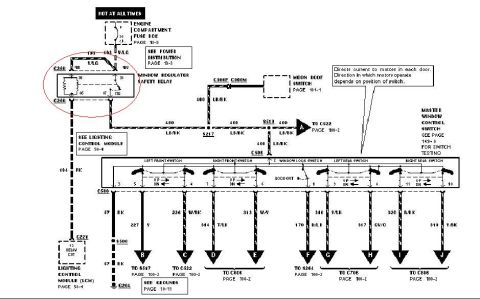


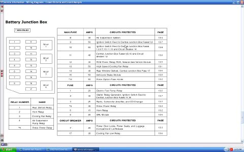
Cooling-fan wiring diagram adding a 10A-fused auxiliary relay (30 to 87A) ahead of high/low fan relays; 50A maxi-fuse, 30A breaker, with 2000 CV relay pin wire colors.
Part of 1992-1997 Ford Crown Victoria Wiring Diagrams
This is a hand-drawn (computer-drawn) wiring diagram showing how to wire an electric cooling fan using a 2000 Crown Victoria (CV) relay center, uploaded to a 1994 Ford Crown Victoria gallery. It depicts a 12V battery feeding a 12V+ constant circuit through a 10 Amp fuse and a 50 Amp Maxi-Fuse, an auxiliary relay (pins 30, 85, 86, 87, 87A), a high speed relay, a low speed relay, and a 30 amp circuit breaker, all feeding an electric fan. The auxiliary relay is triggered by the A/C high pressure switch (Grn/Orn wire): current flows from pin 30 to 87A until the A/C switch trips the coil, then current goes to 87. A legend lists the 2000 CV relay center wire colors: High Speed Relay: Pin 3/30-RD/BK, Pin 5/87-OG/LB, Pin 2/86-LG/VT, Pin 1/85-RD; Low Speed Relay: 30-YE, 87-YE/LB, 86-RD/LB, 85-BK. Notes state the low speed relay ground can go to a temp sensor, a switch, or both (recommending an ON/ON switch so low speed can be activated any time while still auto shutting down on high-side activation), and that pins 85 and 86 are reversed for the relay control center's existing wires.
Is this accurate? Sign in to help verify it.
Frequently asked questions
- What wire colors does the 2000 CV relay center use for the high speed fan relay?
- Per the diagram legend: Pin 3/30 is RD/BK, Pin 5/87 is OG/LB, Pin 2/86 is LG/VT, and Pin 1/85 is RD.
- What wire colors are used on the low speed fan relay?
- Pin 30 is YE (yellow), 87 is YE/LB, 86 is RD/LB, and 85 is BK.
- How does the auxiliary relay work with the A/C system in this diagram?
- Current from pin 30 goes to 87A until the A/C high pressure switch (Grn/Orn wire) trips the relay coil; then current goes to pin 87.
- What fuse and circuit protection is shown in this fan wiring diagram?
- A 10 Amp fuse on the 12V+ constant line, a 50 Amp Maxi-Fuse from the battery, and a 30 amp circuit breaker in the relay circuit.
- How should the low speed relay ground be wired?
- The diagram says to ground the low speed relay to either a temp sensor, a switch, or both, using an ON/ON switch so low speed can be activated any time and still be auto shut down by high side activation.




No comments yet.