Home/
Registry/
Ford/
Crown Victoria/
1992-1997/
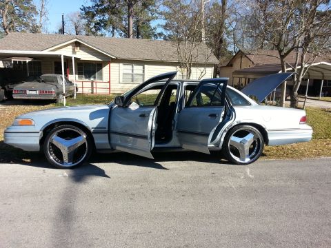
1992 Ford Crown Victoria/
Photo
supermotors.net/registry/media/484927
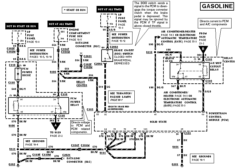
Ford Crown Victoria PCM Power, Ground & BOO Switch Wiring Diagram (Gasoline)
Reference · 1992-1997 Crown VictoriaAll 12 wiring diagrams
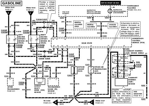
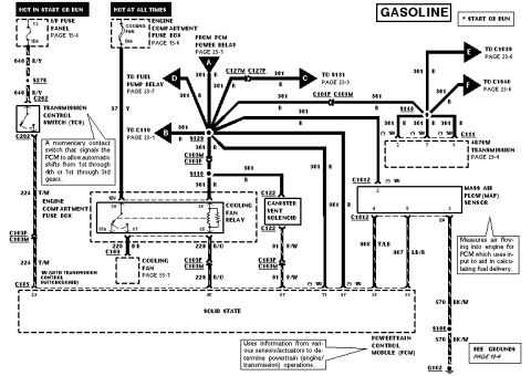
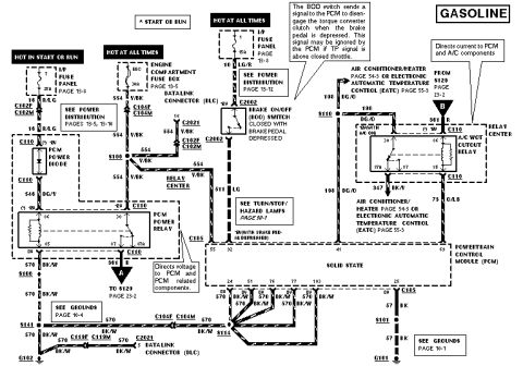
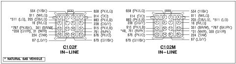
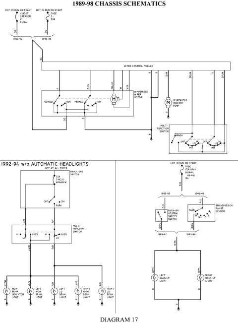
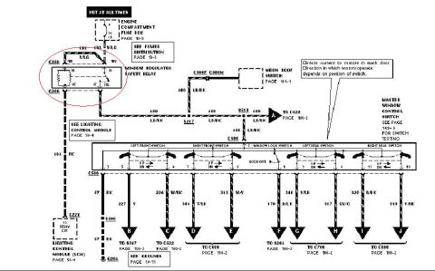
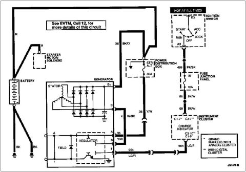
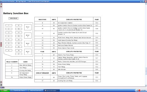


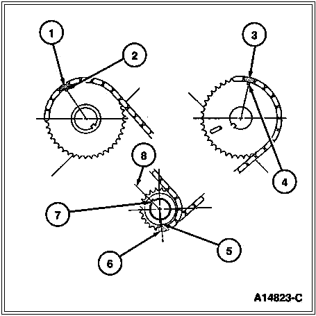
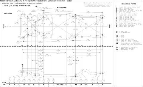
Wiring diagram for a gasoline engine showing PCM power diode, power relay, BOO switch and A/C WOT cutout relay circuits.
Part of 1992-1997 Ford Crown Victoria Wiring Diagrams
This document is a Ford gasoline-engine powertrain control module (PCM) power, ground, and relay wiring diagram. It shows three power feeds: a 25A instrument panel fuse (Hot in Start or Run) feeding circuit 16 R/LG through connectors C102F/C102M to the PCM power diode and PCM power relay; a 20A EEC fuse in the engine compartment fuse box (Hot at All Times) feeding circuit 554 V/BK to the Data Link Connector, relay center, and PCM power relay; and a 15A fuse feeding circuit 10 LG/R to the Brake On/Off (BOO) switch, which sends circuit 511 LG to PCM pin 32 when the brake pedal is depressed (used to disengage the torque converter clutch). The diagram also shows the A/C WOT cutout relay in the relay center with circuits 198 DG/O, 347 BK/Y, and 73 O/LB tied to the air conditioner/heater or EATC systems and PCM pins 73 and 63. Grounding is shown via circuit 570 BK/W from PCM pins 24, 51, 76, 77, and 103 through splices S114, S141, and S106 to grounds G102 and G101, plus circuit 57 BK from pin 25. Cross-references point to power distribution pages 13-5, 13-8, 13-10, 13-12, grounds pages 10-1 and 10-4, and A/C pages 54-3/55-3.
Is this accurate? Sign in to help verify it.
Frequently asked questions
- What fuse powers the EEC/PCM system through the engine compartment fuse box?
- A 20A EEC fuse in the engine compartment fuse box (page 13-5), Hot at All Times, feeding circuit 554 V/BK.
- What does the Brake On/Off (BOO) switch do in this circuit?
- The BOO switch sends a signal to the PCM to disengage the torque converter clutch when the brake pedal is depressed. The PCM may ignore this signal if the TP signal is above closed throttle.
- What wire color and circuit number are the PCM grounds?
- PCM pins 24, 51, 76, 77, and 103 ground through circuit 570 BK/W (black/white) via S114 to grounds G102 and via S141/S106; pin 25 grounds through circuit 57 BK to G101.
- What powers the BOO switch?
- A 15A fuse in the I/P fuse panel (page 13-8), Hot at All Times, on circuit 10 LG/R (light green/red).
- What does the A/C WOT cutout relay connect to?
- It is located in the relay center and connects via circuits 198 DG/O, 347 BK/Y, and 73 O/LB to the air conditioner/heater (page 54-3) or EATC (page 55-3) systems and to the PCM.



No comments yet.