Home/
Registry/
Ford/
Crown Victoria/
1992-1997/
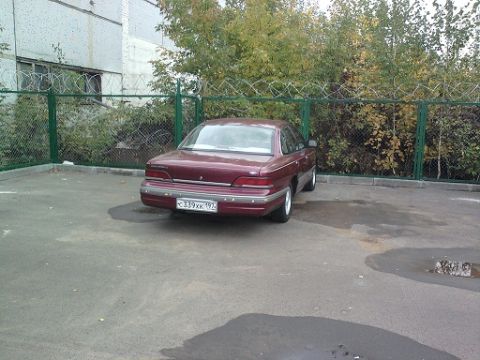
1992 Ford Crown Victoria/
Photo
supermotors.net/registry/media/484930
Ford Fuel Pump Wiring Diagram - Inertia Switch, Relay & Sender Circuit (Gasoline)
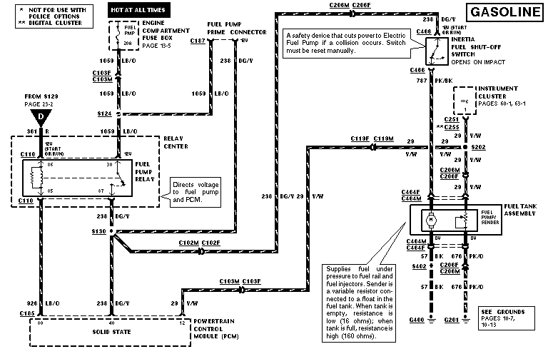
Wiring diagram showing the fuel pump relay, inertia fuel shut-off switch and fuel tank pump/sender circuits.
This document is a Ford factory-style wiring diagram (EVTM page) for the electric fuel pump circuit on a gasoline-engine vehicle. It traces power from a 20A FUEL PMP fuse in the engine compartment fuse box (hot at all times) through circuit 1059 LB/O to the fuel pump relay in the relay center (pins 30, 85, 86, 87), which the diagram notes 'directs voltage to fuel pump and PCM.' Output circuit 238 DG/V runs through the fuel pump prime connector (C187), connectors C102M/C102F and C206M/C206F, to the inertia fuel shut-off switch, described as a safety device that cuts power to the electric fuel pump in a collision and must be manually reset. From the switch, circuit 787 PK/BK feeds the fuel tank assembly's fuel pump and sender via connectors C464F/C464M. The fuel gauge sender is described as a variable resistor on a float: 16 ohms when empty, 160 ohms when full, feeding the instrument cluster on circuit 29 V/W (connectors C251/C255, splice S202). Grounds are 57 BK to G400 and 676 PK/O to G201 via S402. Footnotes indicate the circuit is not for police options and marks digital cluster variations. Cross-references include pages 13-5, 23-2, 60-1, 65-1, 10-7, and 10-13.
Is this accurate? Sign in to help verify it.
Frequently asked questions
- What does the inertia fuel shut-off switch do?
- Per the diagram, it is a safety device that cuts power to the electric fuel pump if a collision occurs, opens on impact, and must be reset manually.
- What fuse powers the fuel pump circuit?
- A 20A 'FUEL PMP' fuse in the engine compartment fuse box, hot at all times (referenced to page 13-5).
- What wire color feeds the fuel pump from the inertia switch?
- Circuit 787 PK/BK (pink/black) runs from the inertia switch connector C466 toward the fuel tank assembly and instrument cluster path.
- What are the fuel sender resistance values?
- The sender is a variable resistor connected to a float: resistance is low (16 ohms) when the tank is empty and high (160 ohms) when the tank is full.
- What does the fuel pump relay do in this circuit?
- The diagram states the fuel pump relay directs voltage to the fuel pump and the PCM; it receives power on circuit 1059 LB/O and outputs on circuit 238 DG/V.
Comments
More from this build




No comments yet.