Home/
Registry/
Ford/
Taurus/
1996-1999/
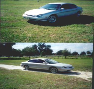
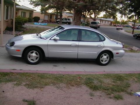
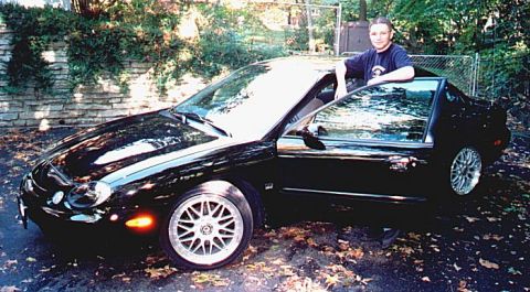
1997 Ford Taurus/
Photo
supermotors.net/registry/media/647861
Ford AX4N Transaxle Solenoid Locations - Shift, TCC & EPC Solenoid Diagram

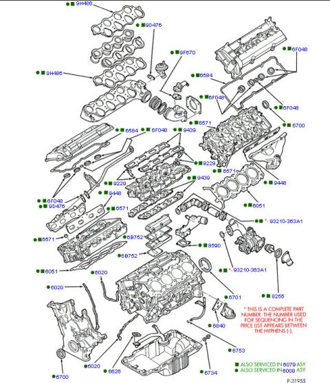
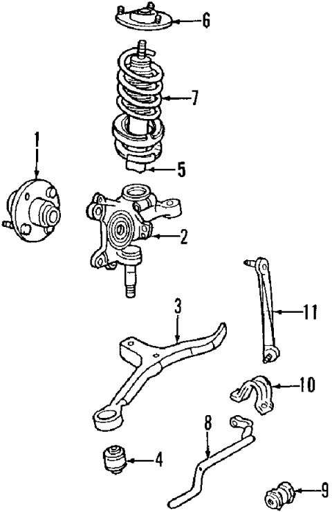
Reference · 1996-1999 TaurusAll 17 exploded parts diagrams
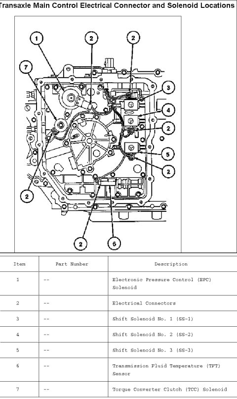
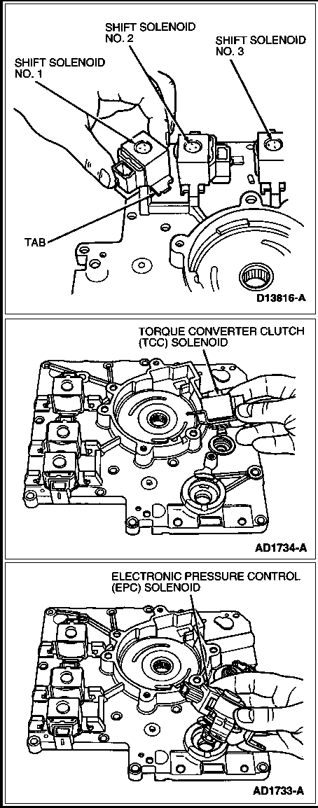


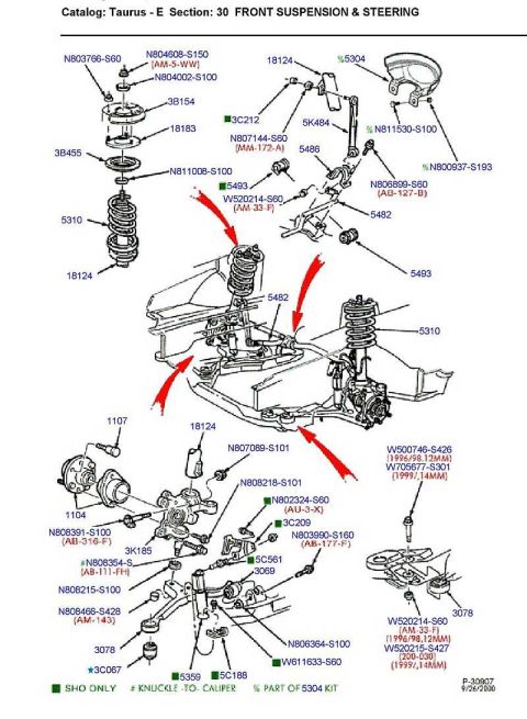
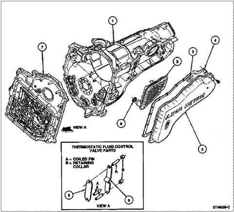



Ford automatic transmission valve-body service illustrations locating Shift Solenoids No. 1/2/3, the Torque Converter Clutch (TCC) solenoid and Electronic Pressure Control (EPC) solenoid.
Part of 1996-1999 Ford Taurus Exploded Parts Diagrams
This document is a three-panel illustrated reference showing the locations of the electrically controlled solenoids on an automatic transaxle valve body (uploaded and labeled as covering the Ford AX4N transaxle, filed under a 1997 Ford Taurus). The top illustration (figure D13816-A) shows a hand positioning or removing Shift Solenoid No. 1, with callouts identifying Shift Solenoid No. 2, Shift Solenoid No. 3, and a retaining TAB on the valve body. The middle illustration (figure AD1734-A) shows a hand installing or removing the Torque Converter Clutch (TCC) Solenoid on the valve body near the large circular pump/converter passage area. The bottom illustration (figure AD1733-A) shows a hand handling the Electronic Pressure Control (EPC) Solenoid at its mounting bore on the same valve body. A reader can learn where each of the five solenoids, Shift Solenoids 1, 2, and 3, the TCC solenoid, and the EPC solenoid, is physically located on the valve body, which is useful for diagnosis and replacement work. The document contains no year, model, torque specifications, or part numbers beyond the figure reference codes.
Is this accurate? Sign in to help verify it.
Frequently asked questions
- What solenoids are shown on the AX4N valve body in this diagram?
- Shift Solenoid No. 1, Shift Solenoid No. 2, Shift Solenoid No. 3, the Torque Converter Clutch (TCC) Solenoid, and the Electronic Pressure Control (EPC) Solenoid.
- Where is the TCC solenoid located?
- The middle illustration (figure AD1734-A) shows the Torque Converter Clutch (TCC) Solenoid being installed/removed by hand on the valve body near the large circular passage area.
- How are the shift solenoids retained?
- The top illustration shows a TAB called out on the valve body near Shift Solenoid No. 1, indicating a retaining tab is used.
- What figure reference numbers appear in this document?
- D13816-A (shift solenoids), AD1734-A (TCC solenoid), and AD1733-A (EPC solenoid).



No comments yet.