Ford Taurus 3.0L 2V Starting System Wiring Diagram - Starter Relay & DTR Sensor

Reference · 1996-1999 TaurusAll 33 wiring diagrams





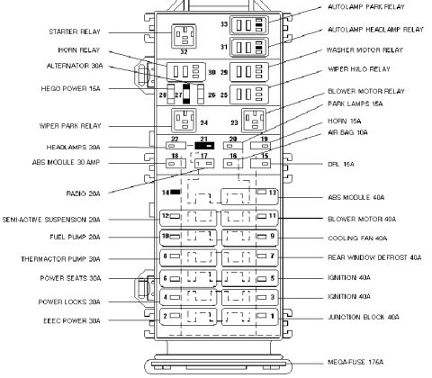
Starting-system wiring diagram showing battery, starter motor relay, DTR sensor and ignition switch circuits.
Part of 1996-1999 Ford Taurus Wiring Diagrams
This document is a starting system wiring diagram for a Ford vehicle with the 3.0L 2V engine (noted "per Ford Powertrain"). It shows the complete starter circuit: battery power feeds through a 40 A fuse in the engine compartment fuse/relay box on circuit 1050 (LG/P) through connector C129 to the starter relay. The relay output travels on circuit 33 (W/PK) through connectors C130M/C130F and C148 to the starter motor/solenoid, which contains pull-in and hold windings. The ignition switch (hot at all times) feeds circuit 32 (R/LB) through connector C293 to fuse 7 (10 A) in the I/P fuse panel, then on circuit 262 (BR/PK) to the Digital Transmission Range (DTR) sensor via connector C171. The DTR sensor completes the start circuit in Park and Neutral (and the back-up lamp circuit), returning on circuit 1039 (T/R) and *33 (W/PK) to the starter relay coil. Grounds are at G104 (circuit 57 BK), with references to grounds pages 10-2, 10-4, and 14-4, power distribution pages 13-1 and 13-5, and component pages 13-3, 13-9, 13-10, and 29-4. Callout notes explain the starter relay and solenoid switch operation.
Is this accurate? Sign in to help verify it.
Frequently asked questions
- What size fuse protects the starter circuit in the engine compartment fuse/relay box?
- A 40 A fuse in the engine compartment fuse/relay box feeds the starter relay on circuit 1050 (LG/P).
- What does the DTR sensor do in the starting circuit?
- Per the diagram's note, the DTR (Digital Transmission Range) sensor completes the start circuit in Park and Neutral, and also completes the back-up lamp circuit.
- What wire color goes from the starter relay to the starter solenoid?
- Circuit 33, a W/PK (white/pink) wire, runs from the starter relay through connectors C130M/C130F and C148 to the starter motor/solenoid.
- Which fuse in the interior fuse panel is in the start circuit?
- Fuse 7, a 10 A fuse in the I/P fuse panel (page 13-10), carries ignition switch start feed on circuit 32 (R/LB) to circuit 262 (BR/PK) toward the DTR sensor.
- What does the starter relay do?
- Per the callout, when energized it provides voltage and current to the starter motor internal relay (solenoid) coil, which then closes a switch to apply battery voltage to the starter motor.

No comments yet.