Ford Taurus Halfshaft ABS Sensor Ring Press Diagram: Tool 206-072

Reference · 1996-1999 TaurusAll 18 service procedures
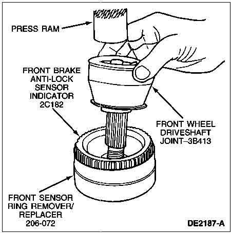
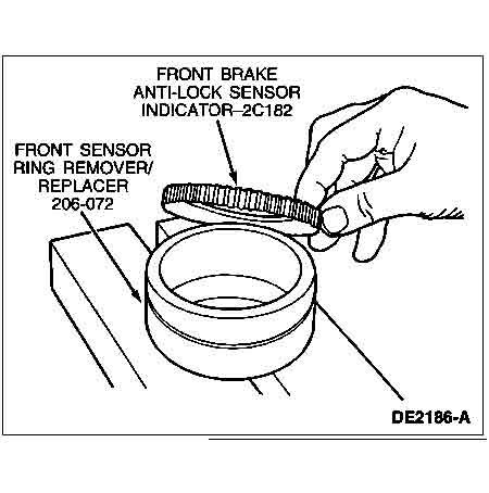
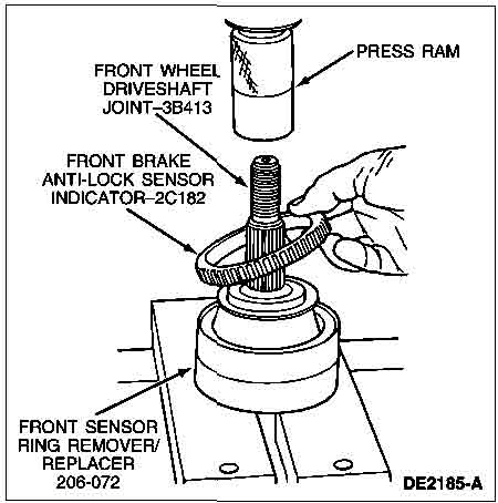
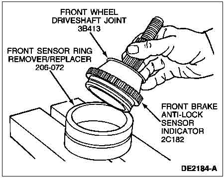
Service-procedure illustration showing a press ram driving the driveshaft joint into the ABS sensor-ring remover/replacer.
Part of 1996-1999 Ford Taurus Service Procedures
This document is a single illustration from a Ford service procedure showing the installation (pressing) of the front brake anti-lock (ABS) sensor indicator ring onto a front wheel driveshaft joint (halfshaft outboard CV joint). The line drawing shows a press ram bearing down on the front brake anti-lock sensor indicator (Ford base part number 2C182), which is being pressed onto the front wheel driveshaft joint (base part number 3B413). The joint's splined stub shaft passes down into the Front Sensor Ring Remover/Replacer special service tool, number 206-072, which supports the assembly in the press. A hand is shown steadying the CV joint during the operation. The figure carries Ford illustration reference DE2187-A. A reader learns which special tool (206-072) is required to remove or install the ABS sensor/tone ring on the halfshaft, that a hydraulic press is used for the operation, and the Ford part group numbers for the sensor indicator ring (2C182) and the driveshaft joint (3B413). No torque values, year/model applicability, or written procedural steps appear on this page; it is purely the labeled diagram accompanying the halfshaft service procedure.
Is this accurate? Sign in to help verify it.
Frequently asked questions
- What special tool is used to remove or install the front ABS sensor ring on the halfshaft?
- The Front Sensor Ring Remover/Replacer, tool number 206-072, is shown supporting the driveshaft joint while the sensor indicator ring is pressed on with a press ram.
- What is the Ford part number for the front brake anti-lock sensor indicator ring?
- The diagram labels the front brake anti-lock sensor indicator with base part number 2C182.
- What part number is given for the front wheel driveshaft joint?
- The front wheel driveshaft joint is labeled 3B413 in the illustration.
- How is the ABS sensor indicator installed on the CV joint?
- Per the diagram, the joint sits in tool 206-072 and a press ram presses the sensor indicator ring onto the front wheel driveshaft joint.


No comments yet.