SuperMotors SuperMotors SUPERMOTORS Search: try “orange Bronco on 35s”
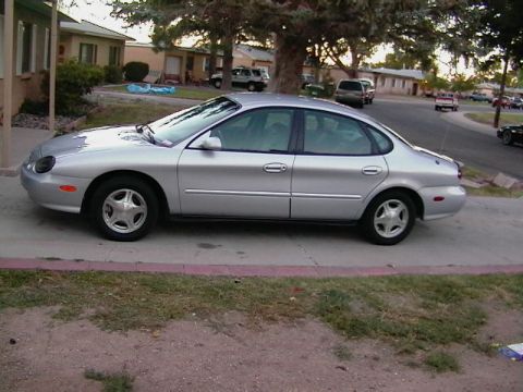
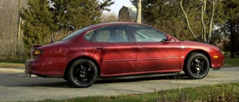
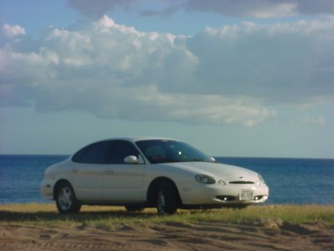
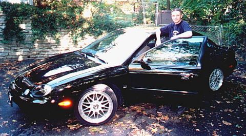
Home/ Registry/ Ford/ Taurus/ 1996-1999/ “My Baby”/ Photo supermotors.net/registry/media/65437

1998 Ford Taurus Halfshaft CV Joint & Boot Diagram - E6715-F Callout Figure

Numbered component diagram of press ram, sensor ring and remover/replacer assembly
Numbered component diagram of press ram, sensor ring and remover/replacer assemblyOriginal file
Numbered component diagram of press ram, sensor ring and remover/replacer assembly

Reference · 1996-1999 TaurusAll 17 exploded parts diagrams

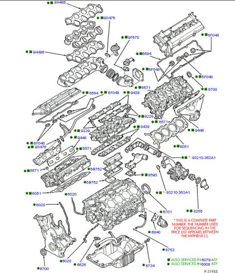
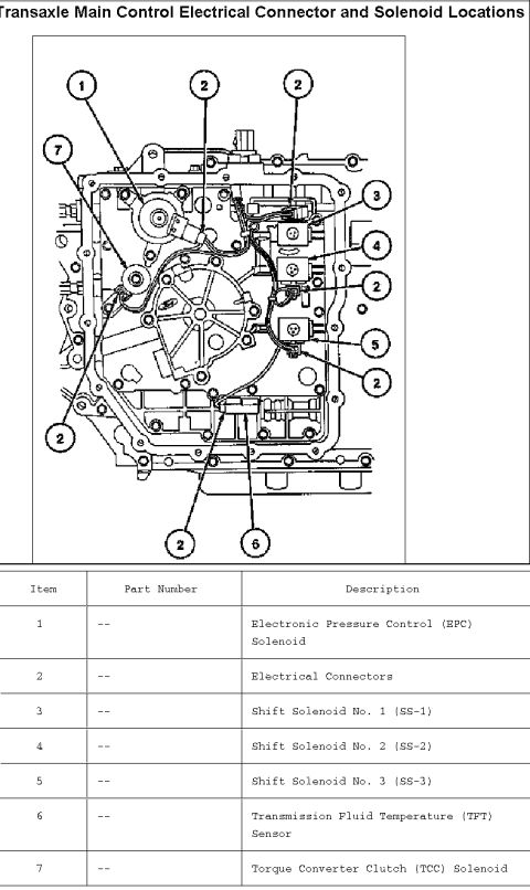
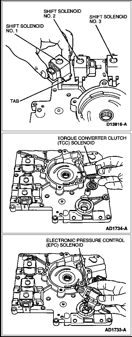
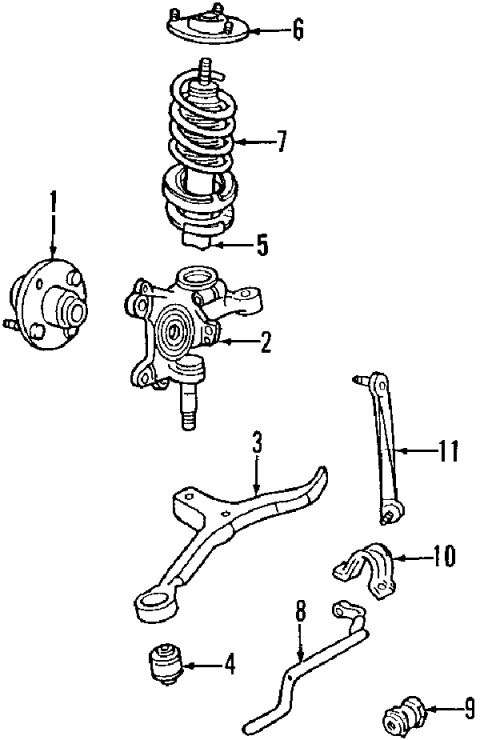
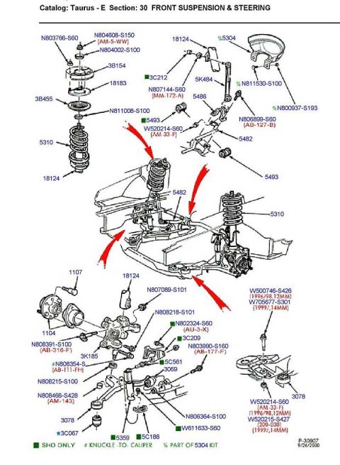
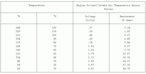
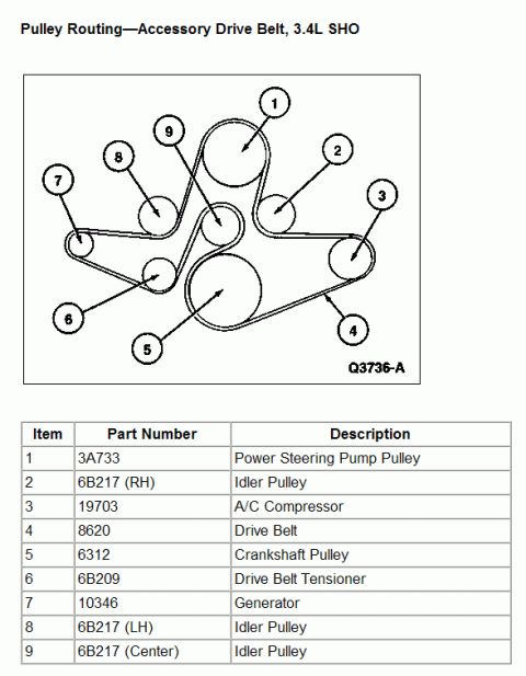
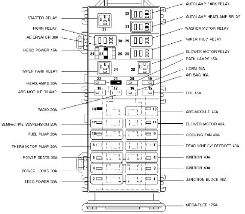
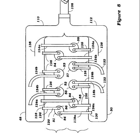
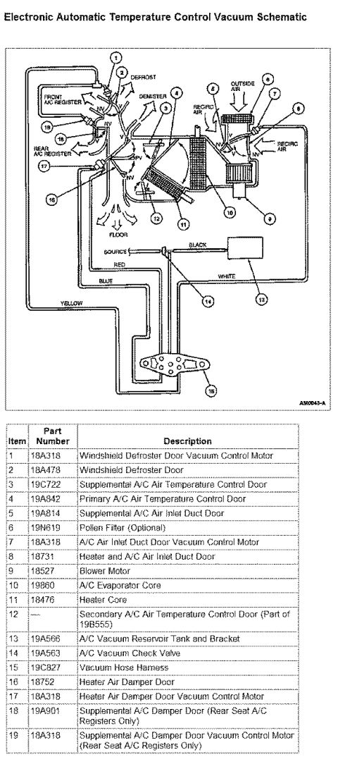
1998 Ford Taurus Halfshaft CV Joint & Boot Diagram - E6715-F Callout Figure 1998 Ford Taurus/Sable Behind Dash Connector Locations - Air Bag Diagnostic Monitor C277 Ford Air Cleaner & Intake 9600 Exploded Parts Diagram (2011 Ford Illustration) Ford Wheels Exploded Parts Diagram - Steel & Alloy Wheels, Covers, Nuts (F0239980-01) Ford Clutch & Manual Transaxle Exploded Parts Diagram - 7B546, 7A508, 7505 Ford Taurus SHO 3.4L V8 Engine Exploded Parts Diagram - Gaskets & Part Numbers Ford AX4N Transaxle Solenoid & Connector Locations Diagram - Taurus Ford AX4N Transaxle Solenoid Locations - Shift, TCC & EPC Solenoid Diagram Ford Taurus 16 & 18 Gallon Fuel Tank Diagram - Fuel Pump & EVAP Part Numbers Ford Taurus Gen 3 Front Suspension Exploded Diagram - Part Numbers (1996-1999) 1997 Ford Taurus Front Suspension Exploded Parts Diagram - Strut, Knuckle, Sway Bar 1996-1998 Ford Taurus Front Suspension Exploded Diagram - Ford Part Numbers 17exploded parts diagrams1996-1999 Ford Taurus More reference Starter Wire Bypass Switch Diagram - 12V Push-Button Starter Circuit (Ford Taurus)Wiring diagram Ford Taurus Halfshaft ABS Sensor Ring Press Diagram: Tool 206-072Service procedure 2004 Ford SVT Mustang Cobra Mystichrome Edition display placard listing specs and featuresBrochure Engine coolant/intake air temperature sensor values table of temperature, voltage and resistanceManual page 1999 Ford Taurus SHO window sticker with equipment list, 16 city / 25 highway MPG and $29,550 MSRPSpec plate Ford Taurus SHO 3.4L V8 Serpentine Drive Belt Routing Diagram & Pulley GuideSchematic 1997 Ford Taurus Gen 3 Engine Compartment Fuse Box Diagram - Fuse & Relay ChartFuse chart V8 Prototype Intake Manifold Runner Horns Patent Drawing: Figure 8 Plenum LayoutBlueprint 1997 Ford Taurus EATC Vacuum Schematic - Hose Routing & Part NumbersVacuum routing

Component breakdown drawing (G6716-E) with numbered callouts 1-5 identifying the press ram, sensor ring and tool parts.

Part of 1996-1999 Ford Taurus Exploded Parts Diagrams

AI caption · Photo 209 of 386

This document is a single black-and-white exploded/detail line drawing, apparently one page of a multi-page halfshaft (CV axle) reference set. It shows the outboard end of a halfshaft: a ribbed (convoluted) CV boot at the top narrowing to a crimped or crosshatched clamp area, seated into a cylindrical joint housing with a knurled/toothed ring (likely an ABS tone ring) around its circumference. Five circled callout numbers (1 through 5) point to different parts of the assembly: callout 1 points to the outer housing/body, callout 2 to the lower ring/band area, callout 3 to the boot seat/insert at the housing mouth, callout 4 to the upper lip of the housing, and callout 5 to the crimped clamp region of the boot. The only text on the page is the Ford-style figure reference number 'E6715-F' in the lower right corner. No legend, part names, part numbers, torque values, or year/model applicability statements are present on this page; the corresponding legend presumably appears on another page of the set. A reader can use this diagram to visually identify the components of the CV joint and boot assembly referenced by numbers elsewhere in the service documentation.

Is this accurate? Sign in to help verify it.

Frequently asked questions

What does this diagram show?
A line drawing of a halfshaft CV joint end, showing the convoluted boot, a crimped boot clamp area, and the joint housing with a toothed ring, marked with five numbered callouts (1-5).
What is the figure reference number on this diagram?
The figure is identified as E6715-F in the lower right corner.
Does this page include a parts legend or part numbers?
No. The only text on the page is the figure number E6715-F; the callouts 1-5 are not labeled here, so the legend must be on another page of the set.
What does callout 5 point to?
Callout 5 points to the crosshatched crimped clamp area where the boot narrows onto the shaft/joint.
Comments

No comments yet.

More 1996-1999 Tauruss