Home/
Registry/
Ford/
Taurus/
1996-1999/
1997 Ford Taurus/
Photo
supermotors.net/registry/media/721501
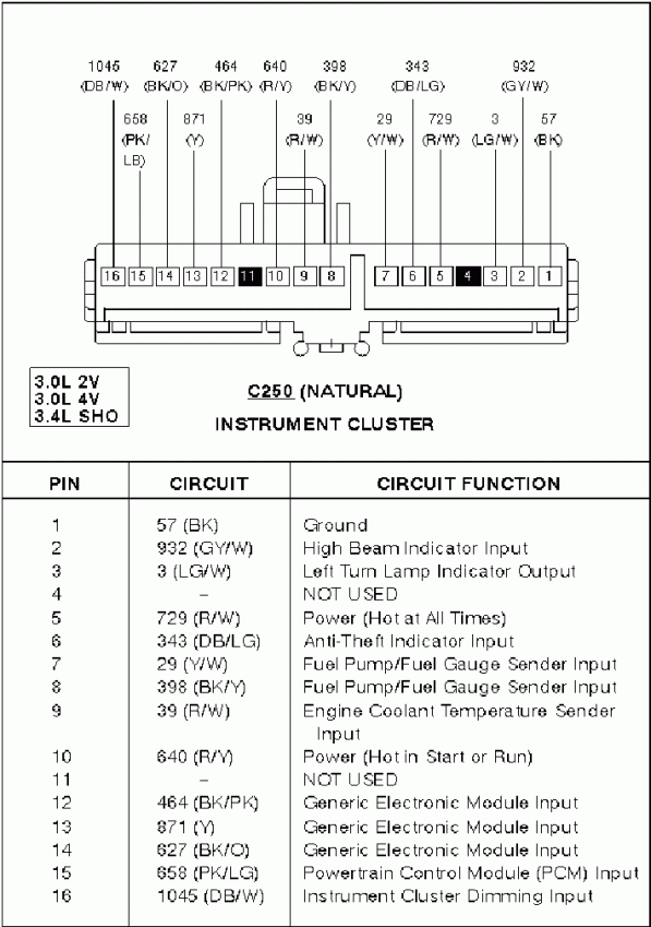
Ford Taurus/SHO Instrument Cluster Connector C250 Pinout - 3.0L & 3.4L SHO
Reference · 1996-1999 TaurusAll 33 wiring diagrams
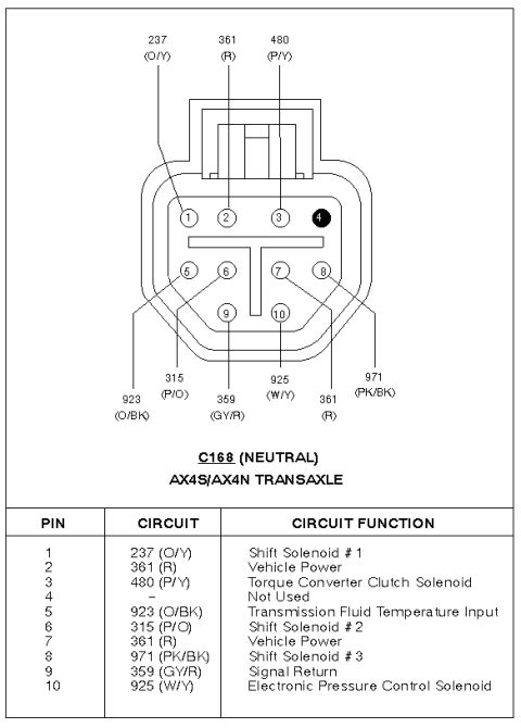
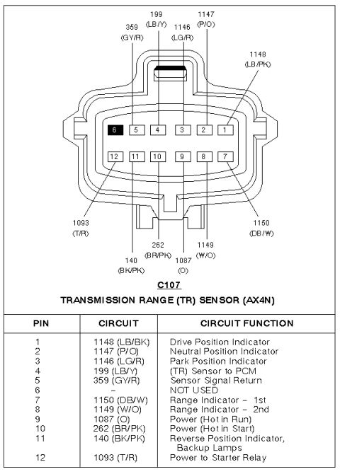
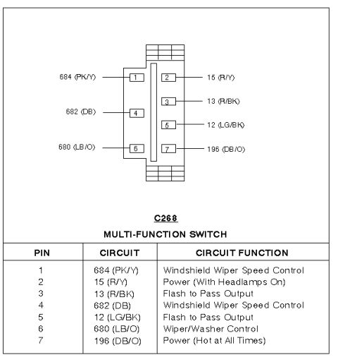
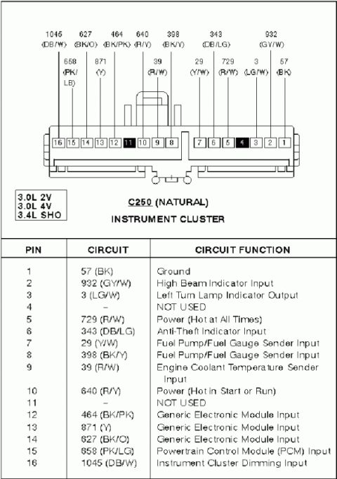
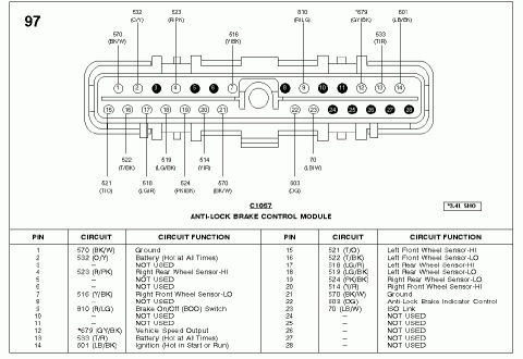
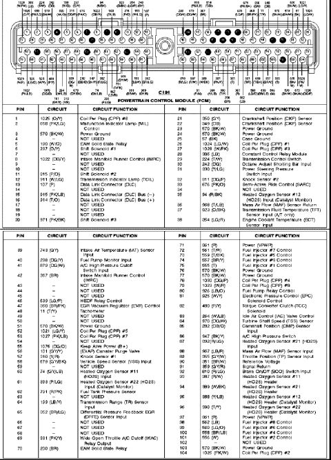
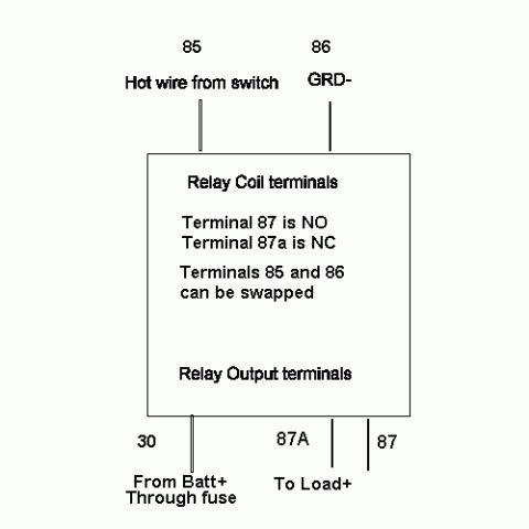

Wiring diagram of the instrument cluster connector C250 showing pin numbers, color-coded circuits and functions.
Part of 1996-1999 Ford Taurus Wiring Diagrams
This document is a connector pinout diagram and table for connector C250 (natural color), the instrument cluster connector, applicable to vehicles with the 3.0L 2V, 3.0L 4V, and 3.4L SHO engines, consistent with a Ford Taurus/SHO application. The upper portion shows the physical 16-pin connector face with each cavity numbered and labeled with its circuit number and wire color code (e.g., 57 BK, 932 GY/W, 640 R/Y, 1045 DB/W). Pins 4 and 11 are shown as not used. The lower table lists each pin, its circuit designation, and its function: pin 1 is ground; pin 2 is the high beam indicator input; pin 3 is the left turn lamp indicator output; pins 5 and 10 are power feeds (hot at all times and hot in start/run, respectively); pin 6 is the anti-theft indicator input; pins 7 and 8 are fuel pump/fuel gauge sender inputs; pin 9 is the engine coolant temperature sender input; pins 12-14 are generic electronic module inputs; pin 15 is a PCM input; and pin 16 is the instrument cluster dimming input. This is a useful reference for diagnosing gauge, indicator lamp, and cluster power/dimming problems, and for identifying wire colors when back-probing the cluster harness.
Is this accurate? Sign in to help verify it.
Frequently asked questions
- What connector is shown in this diagram?
- Connector C250 (Natural), the instrument cluster connector, for 3.0L 2V, 3.0L 4V, and 3.4L SHO engines.
- Which pin on C250 is ground?
- Pin 1, circuit 57 (BK), is ground.
- Which pins provide power to the instrument cluster?
- Pin 5, circuit 729 (R/W), is hot at all times, and pin 10, circuit 640 (R/Y), is hot in start or run.
- Which pins carry the fuel gauge sender signal?
- Pins 7 (circuit 29, Y/W) and 8 (circuit 398, BK/Y) are Fuel Pump/Fuel Gauge Sender Inputs.
- What wire is the instrument cluster dimming input?
- Pin 16, circuit 1045 (DB/W), is the Instrument Cluster Dimming Input.



No comments yet.