Home/
Registry/
Ford/
Mustang/
2005-2014/
“SHELBY GT500”/
Photo
supermotors.net/registry/media/655645
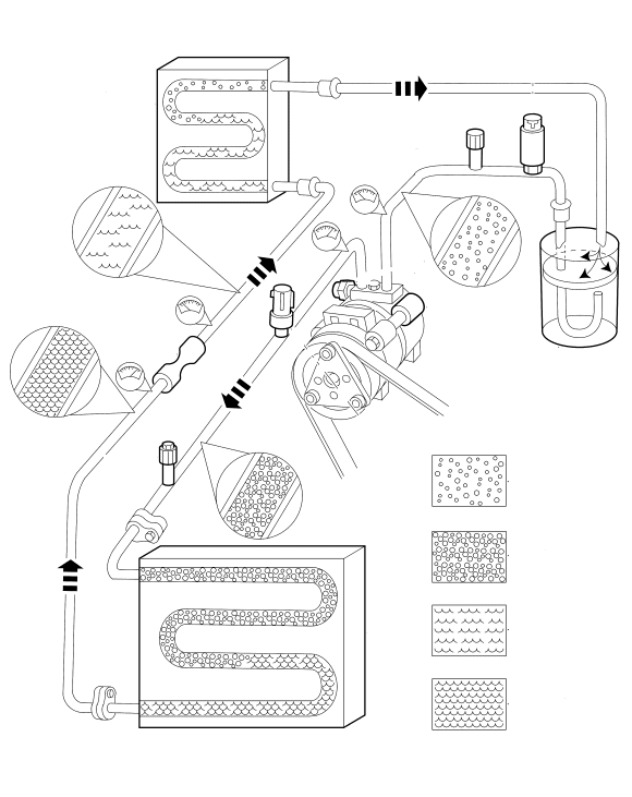
Ford A/C System Refrigerant Flow Diagram - Compressor, Condenser & Evaporator
Reference · 2005-2014 MustangAll 19 schematics
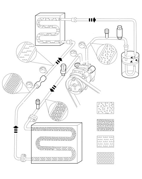









A/C system refrigerant flow schematic showing condenser, compressor, evaporator and accumulator with flow-direction arrows and a state legend.
Part of 2005-2014 Ford Mustang Schematics
This document is a text-free schematic illustration of an automotive air conditioning refrigerant circuit. It depicts the complete refrigerant flow path: a belt-driven compressor at the center, a condenser coil at the top, an evaporator coil at the bottom, and an accumulator/receiver-drier canister with an internal U-tube pickup on the right side. Refrigerant lines connect these components, with bold directional arrows indicating flow direction around the loop. Inline fittings suggest an orifice tube/expansion device and service ports, and two small gauge symbols indicate pressure measurement points. Circular magnified callouts along the lines illustrate the physical state of the refrigerant (vapor with bubbles versus liquid, shown with different hatch and bubble patterns) at each stage of the cycle. A legend of four pattern swatches at the lower right corresponds to these refrigerant states, though it carries no text labels. Because the diagram contains no printed words, numbers, or identifiers, the source year, make, and model cannot be confirmed from the document itself. A reader can learn the general layout and refrigerant flow of a vehicle A/C system, the sequence of components, and how the refrigerant changes state between vapor and liquid through the cycle.
Is this accurate? Sign in to help verify it.
Frequently asked questions
- What does this diagram show?
- It is a schematic of an automotive air conditioning refrigerant system, showing the compressor, condenser, evaporator, accumulator/drier, connecting lines, and flow-direction arrows.
- Does the diagram show the direction of refrigerant flow?
- Yes, bold arrows along the refrigerant lines indicate flow direction around the loop between the condenser, compressor, accumulator, and evaporator.
- What are the circular callouts along the lines?
- They are magnified views showing the refrigerant's physical state (bubbly vapor versus liquid patterns) at different points in the circuit, matching a four-pattern legend at the lower right.
- Does the document list any part numbers or fuse/torque values?
- No. The diagram contains no visible text, part numbers, or values of any kind.






No comments yet.