Home/
Registry/
Ford/
Mustang/
2005-2014/
“SHELBY GT500”/
Photo
supermotors.net/registry/media/655644
Ford RABS Rear Anti-Lock Brake Sensor to PSOM, PCM & Speed Control Block Diagram

Reference · 2005-2014 MustangAll 41 wiring diagrams
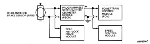
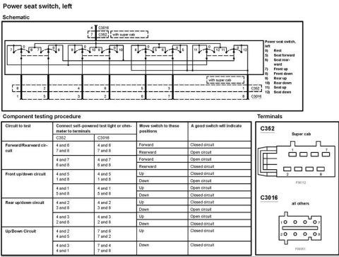
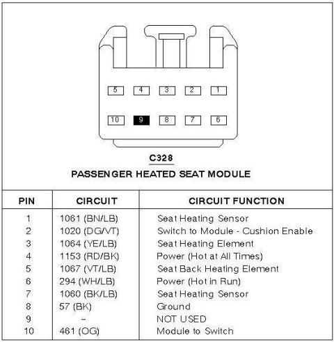
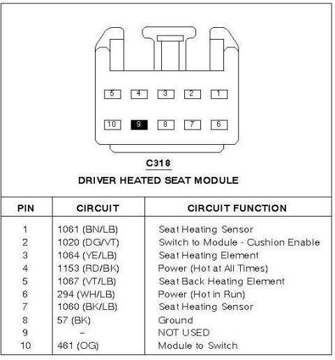









Wiring block diagram showing the rear antilock brake sensor wired to the speedometer/odometer module, powertrain control module and related modules.
Part of 2005-2014 Ford Mustang Wiring Diagrams
This document is a simple functional block diagram showing the signal flow of the Rear Anti-Lock Brake Sensor (RABS) circuit in a Ford vehicle. The diagram depicts the Rear Antilock Brake Sensor (RABS), drawn with positive (+) and negative (−) terminals, feeding its signal to two components: the Programmable Speedometer/Odometer Module (PSOM) and the Rear Anti-Lock Brake Module. The PSOM, in turn, processes the sensor signal and outputs a conditioned vehicle speed signal (shown with a + terminal and a chassis ground reference) to two downstream modules: the Powertrain Control Module (PCM) and the Speed Control Module (cruise control). A reader can learn from this diagram how the rear axle speed sensor signal is shared among the ABS, speedometer, engine management, and cruise control systems, and that the PSOM acts as the intermediary that converts the raw RABS sensor signal for use by the PCM and Speed Control Module. The diagram carries the Ford illustration reference number A15929-C. No wire colors, connector pin numbers, fuse ratings, or specific model-year applicability are given in the image; it is a conceptual signal-routing overview rather than a detailed wiring schematic.
Is this accurate? Sign in to help verify it.
Frequently asked questions
- What does the RABS sensor connect to according to this diagram?
- The Rear Antilock Brake Sensor (RABS) signal goes to the Programmable Speedometer/Odometer Module (PSOM) and to the Rear Anti-Lock Brake Module.
- Where does the PSOM send its output signal?
- The PSOM outputs a signal (shown with a + terminal and ground reference) to the Powertrain Control Module (PCM) and the Speed Control Module.
- What module processes the rear wheel speed signal before it reaches the PCM?
- The Programmable Speedometer/Odometer Module (PSOM) receives the RABS sensor signal and passes the speed signal to the PCM and Speed Control Module.
- Does this diagram show wire colors or connector pins?
- No. It is a block diagram showing only module-to-module signal flow; no wire colors, pin numbers, or fuse information is shown.






No comments yet.