Home/
Registry/
Ford/
Mustang/
2005-2014/
“SHELBY GT500”/
Photo
supermotors.net/registry/media/655673
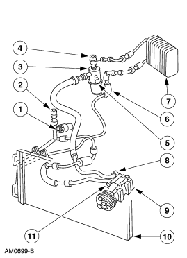
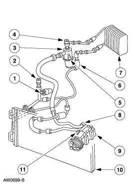
Ford A/C Refrigerant Line & Service Port Diagram - Compressor, Condenser (AM0699-B)
Reference · 2005-2014 MustangAll 19 schematics
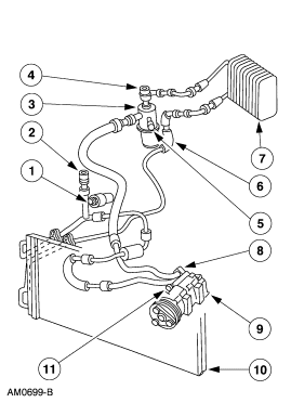
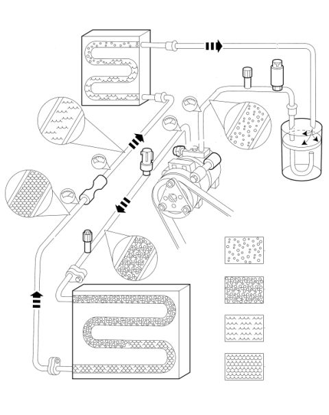
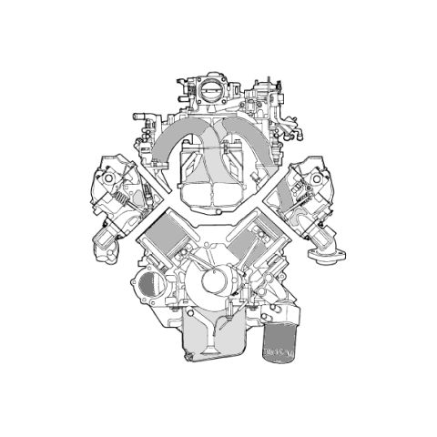
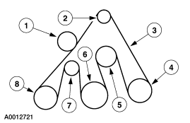









Schematic of air-conditioning refrigerant lines, condenser and fittings with numbered component callouts.
Part of 2005-2014 Ford Mustang Schematics
This document is a black-and-white exploded/component schematic showing an automotive air conditioning refrigerant system layout. Eleven numbered callouts (1 through 11) point to individual components, including what appear to be high-side and low-side service valve fittings on the refrigerant lines (callouts 3, 4, 5, 6 near the valve/manifold assembly), the A/C compressor (callout 9), a condenser or evaporator core at lower left, another heat-exchanger core at right (callout 7) and bottom right (callout 10), and the connecting hose/line assemblies (callouts 2, 8, 11). The drawing carries the Ford illustration reference number AM0699-B in the lower left corner. The uploader's filename 'low and high.gif' suggests the diagram identifies the low-side and high-side A/C service ports. No legend or parts list accompanies the image, so the specific names of the numbered components are not stated within the document itself. A reader can use this diagram to understand the physical routing of the A/C lines and the relative positions of the compressor, condenser, service fittings, and connecting hoses, but would need the companion legend page (not included in this scan) to identify each numbered item by name or part number.
Is this accurate? Sign in to help verify it.
Frequently asked questions
- What does this diagram show?
- It is a numbered schematic (callouts 1-11) of an air conditioning refrigerant system, showing the compressor, heat-exchanger cores, refrigerant lines/hoses, and service valve fittings and their routing.
- Is there a parts legend identifying each numbered callout?
- No. The scan contains only the numbered callouts (1 through 11) and the drawing reference AM0699-B; no legend or component names are printed on this page.
- What is the drawing reference number on this schematic?
- The illustration reference number shown in the lower-left corner is AM0699-B.
- Where are the A/C service fittings located according to the diagram?
- Callouts 3, 4, 5, and 6 point to fittings on the valve/manifold section of the refrigerant lines at the top center of the diagram, consistent with the low-side and high-side service ports suggested by the file name 'low and high'.






No comments yet.