Home/
Registry/
Ford/
Mustang/
2005-2014/
“SHELBY GT500”/
Photo
supermotors.net/registry/media/689480
Ford Mass Air Flow (MAF) Sensor Diagram - Hot Wire, Cold Wire & IAT Thermistor

Reference · 2005-2014 MustangAll 19 schematics

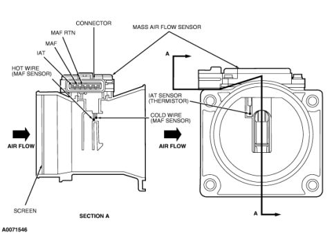









Technical schematic and cross-section of a mass air flow (MAF) sensor showing hot wire, cold wire, IAT thermistor, connector, and air flow direction.
Part of 2005-2014 Ford Mustang Schematics
This document is a labeled cutaway schematic of a Ford Mass Air Flow (MAF) sensor assembly. It shows two views: a side cross-section (labeled "SECTION A") and an end-on view along section line A-A. The left view identifies the sensor's electrical connector and its signal designations, MAF RTN (return), MAF, and IAT, as well as the internal HOT WIRE (MAF SENSOR) and COLD WIRE (MAF SENSOR) sensing elements. Arrows labeled "AIR FLOW" indicate the direction air passes through the sensor body, and a SCREEN is shown at the inlet of the housing. The right view, looking into the circular sensor bore, points out the IAT SENSOR (THERMISTOR), which is integrated into the mass air flow sensor assembly. The illustration reference number A0071546 appears in the lower left corner. A reader can learn the internal construction of the MAF sensor, the location of the hot-wire and cold-wire sensing elements, the fact that the intake air temperature (IAT) thermistor is built into the MAF sensor, the connector terminal functions, and the correct orientation of airflow through the unit. No year, model, engine, part number, or specification data is stated on the drawing itself.
Is this accurate? Sign in to help verify it.
Frequently asked questions
- Where is the IAT sensor located on this Ford MAF sensor?
- The diagram shows the IAT sensor (thermistor) is integrated inside the mass air flow sensor housing, visible in the end view of the sensor bore.
- What signals are on the MAF sensor connector in this diagram?
- The connector callouts identify MAF RTN, MAF, and IAT terminals.
- What sensing elements are inside the MAF sensor?
- The cutaway shows a hot wire (MAF sensor) and a cold wire (MAF sensor) element positioned in the airflow path.
- Which direction does air flow through the sensor?
- Arrows labeled 'AIR FLOW' show air entering through the screened inlet end and passing through the sensor body past the hot and cold wires.
- Is there a screen on the MAF sensor?
- Yes, the diagram labels a screen at the inlet side of the sensor housing.






No comments yet.