Home/
Registry/
Ford/
Mustang/
2005-2014/
“SHELBY GT500”/
Photo
supermotors.net/registry/media/689178
Ford 4x4 Components Diagram E9673-A - Axle Actuator & Line Routing Illustration

Reference · 2005-2014 MustangAll 44 exploded parts diagrams
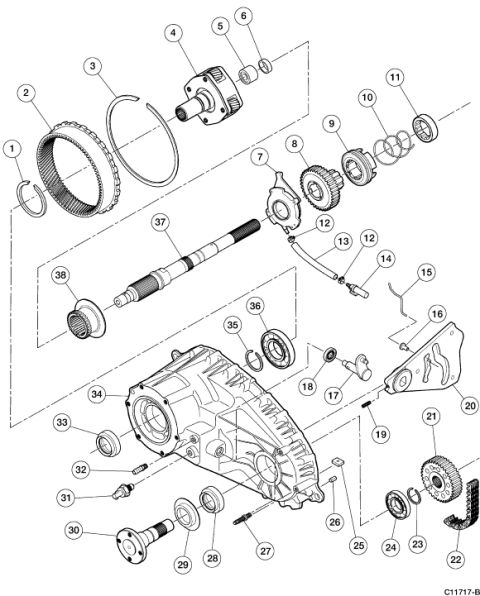
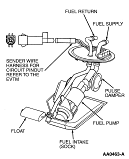
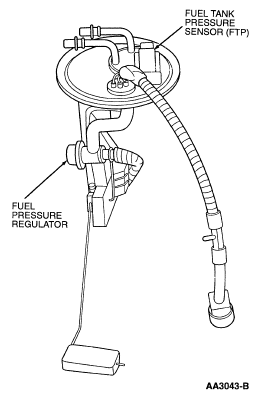
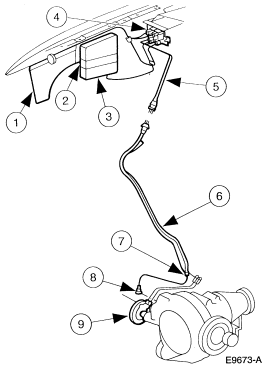
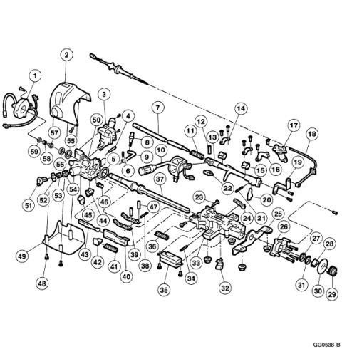
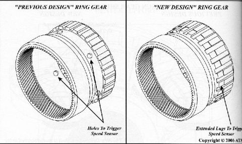
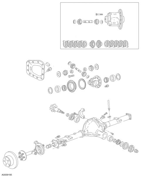
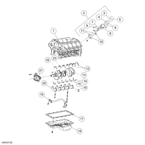
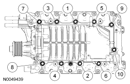
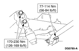
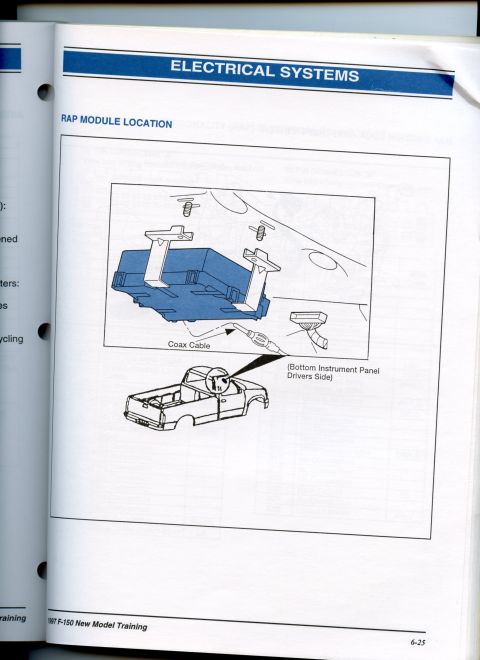
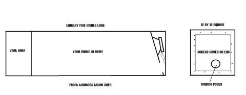
Exploded parts breakdown showing a canister, hoses, and related front-axle components with numbered callouts.
Part of 2005-2014 Ford Mustang Exploded Parts Diagrams
This document is a single-page illustration (figure ID E9673-A) showing an automotive component layout with nine numbered callouts. The upper portion of the diagram depicts components mounted near a vehicle frame or firewall area, including what appears to be a bracket or shield (callouts 1 and 2), a module or solenoid box (callout 3), an electrical connector (callout 4), and a wiring or vacuum line connector (callout 5). A long line or harness (callout 6) routes downward to a lower assembly resembling an axle or transfer-case-mounted component (callout 9), with additional fittings identified by callouts 7 and 8. No legend, parts list, part numbers, torque specifications, or descriptive text accompanies the callouts in this scan, so the reader can learn the physical routing and relative locations of these components but not their names or specifications from this page alone. Based on the uploader's filename, the diagram relates to 4x4 drivetrain components (likely vacuum/electrical actuation for a front axle), but the document itself contains no year, make, model, or system labels. The only printed text is the Ford-style figure reference number E9673-A.
Is this accurate? Sign in to help verify it.
Frequently asked questions
- What does diagram E9673-A show?
- It shows a component layout with nine numbered callouts, including frame-mounted parts, an electrical connector, a long line or harness routing down to an axle-mounted assembly. The scan contains no legend identifying the numbered parts.
- Does this diagram include part numbers or a parts legend?
- No. The only printed text visible is the figure reference number E9673-A and the callout numbers 1 through 9; no legend, part numbers, or torque values are shown.
- How many components are identified in the diagram?
- Nine components are marked with numbered callouts (1 through 9).
- What is the figure reference number of this illustration?
- E9673-A.
No comments yet.