Home/
Registry/
Ford/
Mustang/
2005-2014/
“SHELBY GT500”/
Photo
supermotors.net/registry/media/722800
Ford Turn Signal/Stop/Hazard Lamps Wiring Diagram 090-001 - Flasher Relay Circuit

Reference · 2005-2014 MustangAll 41 wiring diagrams
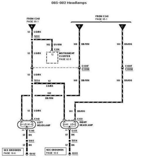
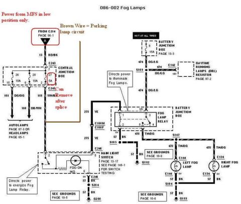
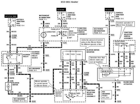
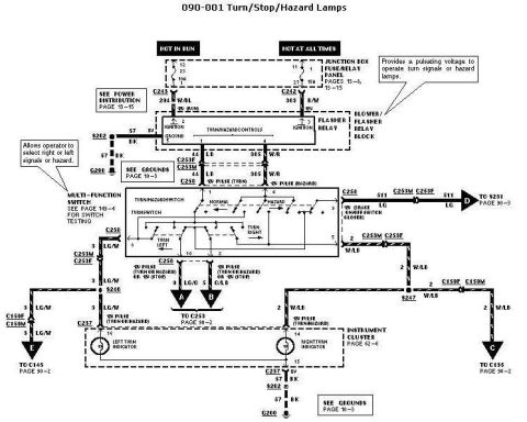










Wiring diagram for turn, stop, and hazard lamps showing the multi-function switch, flasher relay, indicators, and color-coded circuits.
Part of 2005-2014 Ford Mustang Wiring Diagrams
This document is a Ford factory-style wiring diagram, page 090-001, covering the Turn/Stop/Hazard Lamps circuit. It shows power distribution from the Junction Box Fuse/Relay Panel with two feeds: a HOT IN RUN circuit and a HOT AT ALL TIMES circuit (with a 15A fuse noted at position 27). Power passes through connectors C243 (circuit 294 W/BL, Ignition Run) and C242 (circuit 383 R/W) into the Blower/Flasher Relay Block, which contains the flasher relay that 'provides a pulsating voltage to operate turn signals or hazard lamps.' Output circuits 44 LB (turn pulse) and 385 W/R (hazard pulse) feed the Multi-Function Switch (turn/hazard switch) via connectors C253F/C253M and C258. Switch outputs include 511 LG (brake on/off switch), 2 W/LB and 3 LG/W (left/right turn or hazard pulses), and 9 LG/O and 5 O/LB (rear lamp feeds). The diagram also shows the instrument cluster left and right turn indicators via connector C237, and grounds at G200 through splice S202 (circuit 57 BK). Cross-references point to Power Distribution (page 13-15), Grounds (page 10-3), switch testing (page 149-4), instrument cluster (page 62-6), and continuation pages 90-2 and 90-3.
Is this accurate? Sign in to help verify it.
Frequently asked questions
- What wire color carries the turn signal pulse from the flasher relay to the multi-function switch?
- Circuit 44 LB (light blue) carries the 'B' pulse (turn), and circuit 385 W/R (white/red) carries the 'B' pulse (hazard) from the flasher relay block to the turn/hazard switch through connectors C253F/C253M and C258.
- What component produces the flashing of the turn signals and hazards?
- The flasher relay inside the Blower/Flasher Relay Block provides a pulsating voltage to operate the turn signals or hazard lamps.
- Where does the turn/hazard circuit get its power?
- From the Junction Box Fuse/Relay Panel: a HOT IN RUN feed (fuse 12, circuit 294 W/BL via C243) and a HOT AT ALL TIMES feed (fuse 27, 15A, circuit 383 R/W via C242).
- Where is the circuit grounded?
- Ground is at G200 through circuit 57 BK (black) via splice S202, for both the flasher relay block and the instrument cluster (C237 pin 16). See Grounds, page 10-3.
- Where can I find testing procedures for the multi-function switch?
- The diagram references page 149-4 for multi-function switch testing.






No comments yet.