Home/
Registry/
Ford/
Mustang/
2005-2014/
“SHELBY GT500”/
Photo
supermotors.net/registry/media/722801
Ford Heater Wiring Diagram 053-001 - Blower Motor, Resistor & Blend Door Circuit

Reference · 2005-2014 MustangAll 41 wiring diagrams
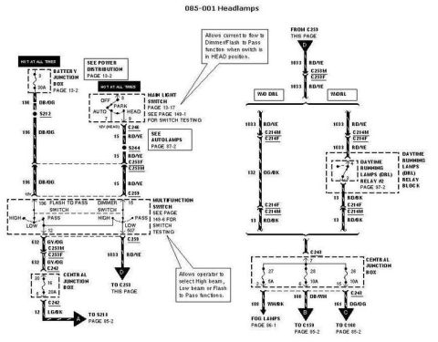
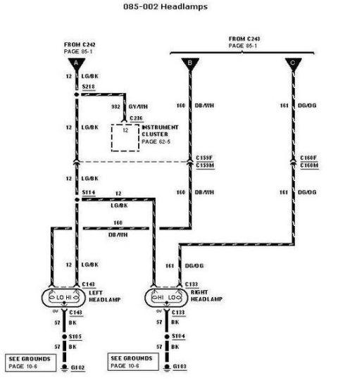
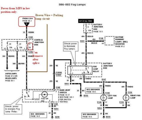
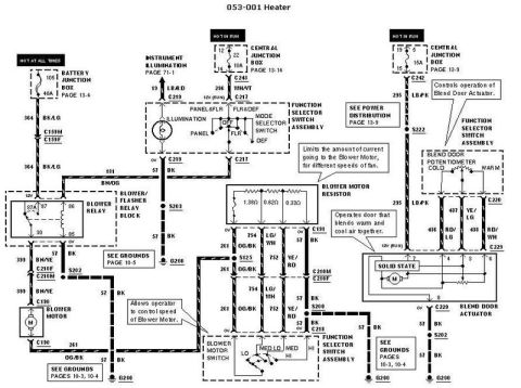
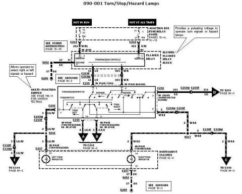
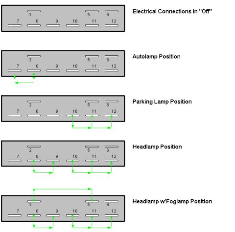
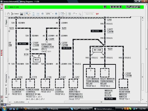










Wiring diagram for the heater system showing blower motor, blower resistor, function selector switch, and blend door actuator with color-coded wires.
Part of 2005-2014 Ford Mustang Wiring Diagrams
This is page 053-001, "Heater," from a Ford factory wiring diagram manual. It shows the complete electrical circuit for a manual heater/HVAC system, including power feeds (a 40A fuse in the Battery Junction Box hot at all times, plus 10A and 15A fuses in the Central Junction Box hot in run), the blower relay in the blower/flasher relay block, the blower motor, the blower motor resistor (with resistance values 1.38Ω, 0.62Ω, and 0.33Ω for fan speeds), the blower motor switch (LO, MED LO, MED HI, HI), the function/mode selector switch with instrument illumination, the blend door potentiometer, and the solid-state blend door actuator. Wire circuit numbers and color codes are labeled throughout (e.g., 364 BK/LG battery feed, 399 BN/YE to the blower motor, 754 LG/WH and 752 YE/RD resistor circuits, 261 OG/BK, 436 RD/LG, 437 YE/LG, 438 RD/WH blend door circuits). Connector identifiers (C130, C159, C191, C210, C217-C220, C223, C242/C243), splices (S125, S200, S202, S203, S222), and grounds (G200) are shown, with cross-references to power distribution and grounds pages. Explanatory callouts describe the function of the resistor, blower switch, and blend door actuator.
Is this accurate? Sign in to help verify it.
Frequently asked questions
- What are the resistance values of the blower motor resistor?
- The blower motor resistor has three elements: 1.38Ω, 0.62Ω, and 0.33Ω, which limit current to the blower motor for the different fan speeds.
- What fuse powers the blower motor circuit?
- A 40A fuse (position 105) in the Battery Junction Box, which is hot at all times, feeds the blower relay via circuit 364 BK/LG.
- What wire feeds the blower motor from the relay?
- Circuit 399 BN/YE runs from the blower relay through connectors C210F/C210M and C130 to the blower motor; the motor return is 261 OG/BK.
- What circuits connect to the blend door actuator?
- The blend door actuator connects via C223 with circuits 437 YE/LG, 436 RD/LG, and 438 RD/WH from the blend door potentiometer, plus a 295 LB/PK 12V run feed and 57 BK ground to S202/G200.
- What fan speed positions does the blower motor switch have?
- The blower motor switch in the function selector switch assembly has LO, MED LO, MED HI, and HI positions.






No comments yet.