Home/
Registry/
Ford/
Mustang/
2005-2014/
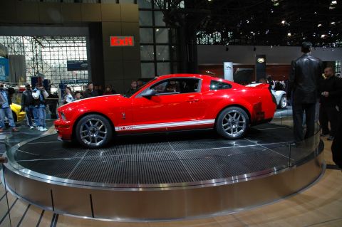
“SHELBY GT500”/
Photo
supermotors.net/registry/media/724082
Ford Headlamp Wiring Diagram 085-002 - Circuits 12, 160, 161, Grounds G102/G103

Reference · 2005-2014 MustangAll 41 wiring diagrams
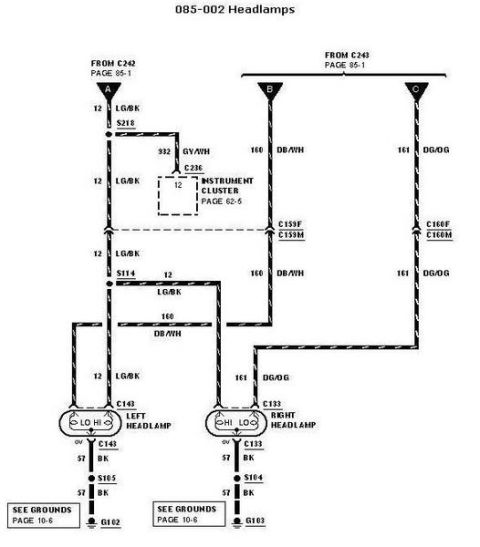

Wiring diagram for headlamps showing left and right headlamp connectors, instrument cluster, grounds, and color-coded circuits.
Part of 2005-2014 Ford Mustang Wiring Diagrams
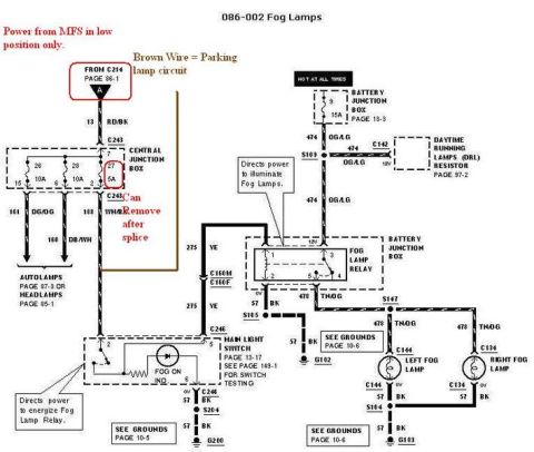
This is page 085-002 of a Ford factory-style wiring diagram covering the headlamps circuit. It shows power feeds arriving from connectors C242 and C243 (referenced on page 85-1) through three circuit branches labeled A, B, and C. Circuit 12 (LG/BK, light green/black) feeds low beam power, passing through splice S218, inline connector C159F/C159M, and splice S114 before reaching the left headlamp at connector C143; a tap of circuit 932 (GY/WH) goes through C236 to the instrument cluster (page 62-5), presumably for the high-beam indicator. Circuit 160 (DB/WH, dark blue/white) and circuit 161 (DG/OG, dark green/orange) carry the other beam feeds through C159F/C159M and C160F/C160M to the left headlamp (C143) and right headlamp (C133). Both headlamps ground through circuit 57 (BK, black): the left headlamp through splice S105 to ground G102, and the right headlamp through splice S104 to ground G103, with a note to see grounds on page 10-6. The diagram lets a reader trace wire colors, circuit numbers, connector and splice IDs, and ground points for diagnosing headlamp low/high beam faults.
Is this accurate? Sign in to help verify it.
Frequently asked questions
- What wire colors feed the headlamps in this diagram?
- Circuit 12 is LG/BK (light green/black), circuit 160 is DB/WH (dark blue/white), and circuit 161 is DG/OG (dark green/orange). Ground circuit 57 is BK (black).
- What are the headlamp connector numbers?
- The left headlamp uses connector C143 and the right headlamp uses connector C133. Power comes from C242 and C243 (page 85-1), through inline connectors C159F/C159M and C160F/C160M.
- Where do the headlamps ground?
- Both headlamps ground on circuit 57 BK. The left headlamp goes through splice S105 to ground G102; the right headlamp goes through splice S104 to ground G103. See grounds page 10-6.
- What circuit connects the headlamps to the instrument cluster?
- Circuit 932 GY/WH taps off splice S218 and runs through connector C236 to the instrument cluster pin 12 (page 62-5).
- What splices are used in the headlamp circuit?
- Splices shown are S218 and S114 on the LG/BK circuit 12 feed, and S105 and S104 on the BK circuit 57 ground paths.
No comments yet.