Home/
Registry/
Ford/
Bronco/
1992-1996/
“Black Iron Horse”/
Photo
supermotors.net/registry/media/755031
1996 Ford Bronco Transmission Valve Body Bolt Tightening Sequence Diagram
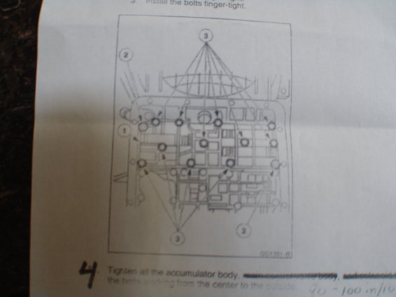
Service procedure figure showing the accumulator body bolt-tightening sequence working from the center to the outside.
Part of 1992-1996 Ford Bronco Service Procedures
This is one page of a scanned automotive transmission service procedure, apparently for reassembling a valve body / accumulator body onto an automatic transmission. The page shows step 3, instructing the technician to install the bolts finger-tight, followed by a large exploded/overhead diagram of the valve body with numbered callouts (1, 2, and 3) identifying different groups of bolt locations. The diagram carries a figure reference code (GC1361-B, partially legible). Step 4 instructs the technician to tighten all the accumulator body bolts, working from the center to the outside; portions of this step's text have been deliberately struck out by hand (apparently references to the main control valve body and solenoid components that do not apply). A handwritten torque annotation of "90 - 100 in/lb" appears at the bottom edge, presumably the tightening specification for these bolts. The page is part of a multi-page set uploaded to a 1996 Ford Bronco gallery; the page itself does not state a year, model, or transmission type. A reader can learn the bolt installation sequence approach (finger-tight first, then torque from center outward) and the handwritten torque value.
Is this accurate? Sign in to help verify it.
Frequently asked questions
- How should the valve body / accumulator body bolts be installed?
- Per step 3, install the bolts finger-tight first.
- In what order should the accumulator body bolts be tightened?
- Step 4 says to tighten the bolts working from the center to the outside.
- What torque value is noted for the bolts?
- A handwritten annotation on the page reads 90 - 100 in/lb.
- What do the numbered callouts 1, 2, and 3 in the diagram indicate?
- They identify different groups of bolt locations on the valve body / accumulator body shown in the overhead diagram.
Comments
More from this build







No comments yet.