Home/
Registry/
Ford/
Bronco/
1978-1979/
1979 Ford Bronco/
Photo
supermotors.net/registry/media/785269
DIY Coilover Diagram - Heim Joints, Sliding Tube & Coil Spring Design (Bronco)

Reference · 1978-1979 BroncoAll 79 exploded parts diagrams

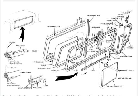
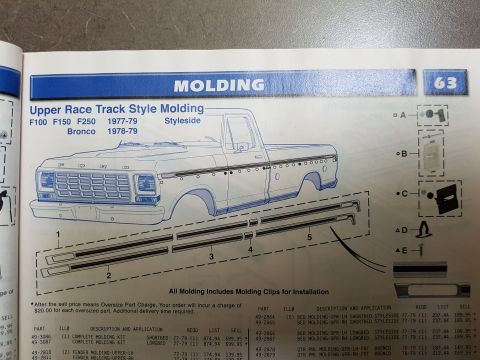
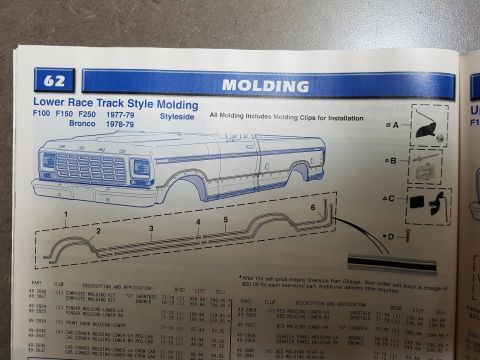
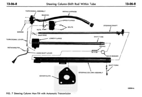
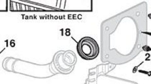
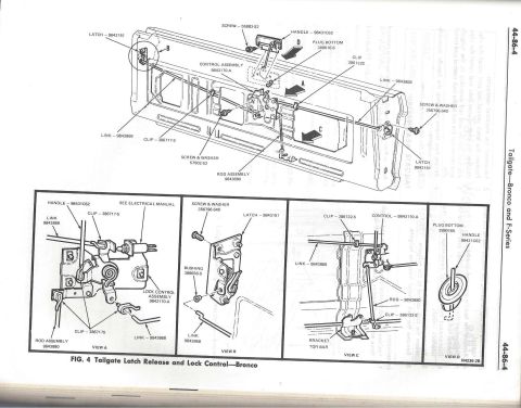
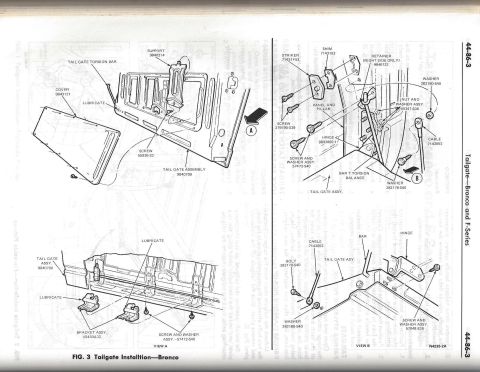
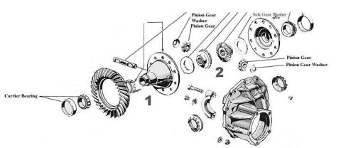



Labeled component diagram of a coilover shock showing Heim joints, coil pockets, sliding tube and steel shaft.
Part of 1978-1979 Ford Bronco Exploded Parts Diagrams
This document is a simple hand-drawn diagram illustrating a do-it-yourself coilover shock/spring assembly design, uploaded to a 1979 Ford Bronco gallery under the filename 'Coilovers.jpg'. The drawing shows a coil spring (depicted in blue) wrapped around a two-piece telescoping center structure. Callout labels identify seven components: heim joints at both the top and bottom mounting ends; 'Original Coil Pockets' (spring perches/plates) at the top and bottom of the coil; a 'Heavy Wall tube (1/8 inch)' forming the upper body of the assembly; a 'Sliding Tube & coil joint' at the middle where the upper tube meets the lower section (shown with a gray collar/bushing); and a 'High strength steel shaft' forming the lower half that slides within the tube. The diagram conveys the basic concept of converting a standard coil spring setup into a coilover-style unit by adding a sliding tube-and-shaft guide through the coil, retaining the original coil pockets and mounting via heim joints. No part numbers, dimensions (other than the 1/8-inch tube wall thickness), torque specifications, or vehicle-specific applicability information is provided. A reader can learn the general component layout and construction concept of this homemade coilover design.
Is this accurate? Sign in to help verify it.
Frequently asked questions
- What wall thickness is the tube used in this coilover design?
- The diagram labels it a 'Heavy Wall tube (1/8 inch)', indicating a 1/8-inch wall thickness.
- How is the coilover mounted at each end?
- Heim joints are shown and labeled at both the top and bottom ends of the assembly.
- What retains the coil spring at each end?
- The diagram labels 'Original Coil Pockets' at both the top and bottom of the coil spring.
- What connects the upper tube to the lower shaft?
- A 'Sliding Tube & coil joint' is shown in the middle of the assembly, joining the heavy wall tube to the high strength steel shaft.
- What material is the lower shaft?
- It is labeled as a 'High strength steel shaft'.






No comments yet.