Home/
Registry/
Ford/
Bronco/
1980-1986/
“Still Pending”/
Photo
supermotors.net/registry/media/825061
Ford 300 Inline Six Manifold Removal/Install & Bolt Torque Sequence - Manual Pg 71
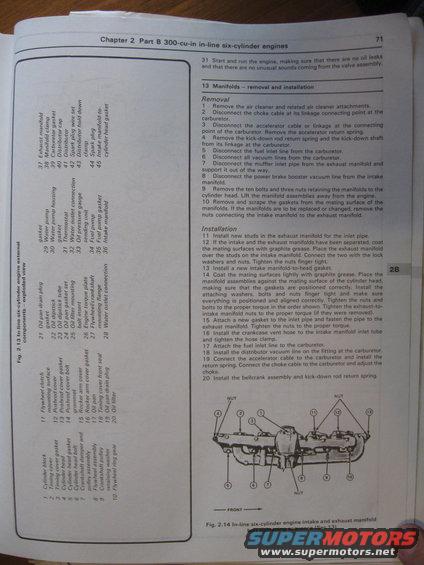
Haynes page for the Ford 300 cu-in inline-six listing external-component callouts (manifolds, water pump, distributor) with intake/exhaust manifold removal and installation steps.
This is page 71 from a Haynes-style repair manual, Chapter 2 Part B, covering the 300-cu-in in-line six-cylinder engine. The page concludes a prior procedure (step 31: run the engine and check for oil leaks and unusual valve noise), then presents Section 13, 'Manifolds: removal and installation.' Removal steps 1-10 cover taking off the air cleaner, disconnecting the choke and accelerator cables, kick-down rod, fuel inlet line, vacuum lines, muffler inlet pipe, and power brake booster vacuum line, then removing the ten bolts and three nuts holding the manifolds to the cylinder head. Installation steps 11-20 cover installing new studs, coating mating surfaces with graphite grease, using a new intake manifold-to-head gasket, tightening fasteners in the proper sequence, and reconnecting fuel, vacuum, and throttle linkages. The page also includes the legend for Fig. 2.13 (in-line six-cylinder engine external components exploded view), listing 45 numbered parts from cylinder block through intake manifold-to-cylinder head gasket, and Fig. 2.14, a diagram of the intake and exhaust manifold bolt tightening sequence with positions numbered 1-13 and nut locations marked, oriented relative to the front of the engine.
Is this accurate? Sign in to help verify it.
Frequently asked questions
- How many fasteners hold the manifolds to the cylinder head on the Ford 300 inline six?
- Ten bolts and three nuts retain the manifolds to the cylinder head (Removal step 9).
- What should be applied to the manifold mating surfaces during installation?
- Coat the mating surfaces lightly with graphite grease before placing the manifold assemblies against the cylinder head (steps 12 and 14).
- Is there a specific tightening order for the intake and exhaust manifold bolts?
- Yes. Fig. 2.14 shows the intake and exhaust manifold bolt tightening sequence, numbered 1 through 13, with nut positions marked and the front of the engine indicated.
- What must be disconnected at the carburetor before removing the manifolds?
- The choke cable, accelerator cable or linkage (and its return spring), the kick-down rod return spring and kick-down shaft, the fuel inlet line, and all vacuum lines.
- What gasket is needed when installing the intake manifold?
- Install a new intake manifold-to-head gasket (step 13), and attach a new gasket to the inlet pipe when fastening it to the exhaust manifold (step 15).
Comments
More from this build












No comments yet.