Home/
Registry/
Ford/
Bronco/
1980-1986/
“Still Pending”/
Photo
supermotors.net/registry/media/825044
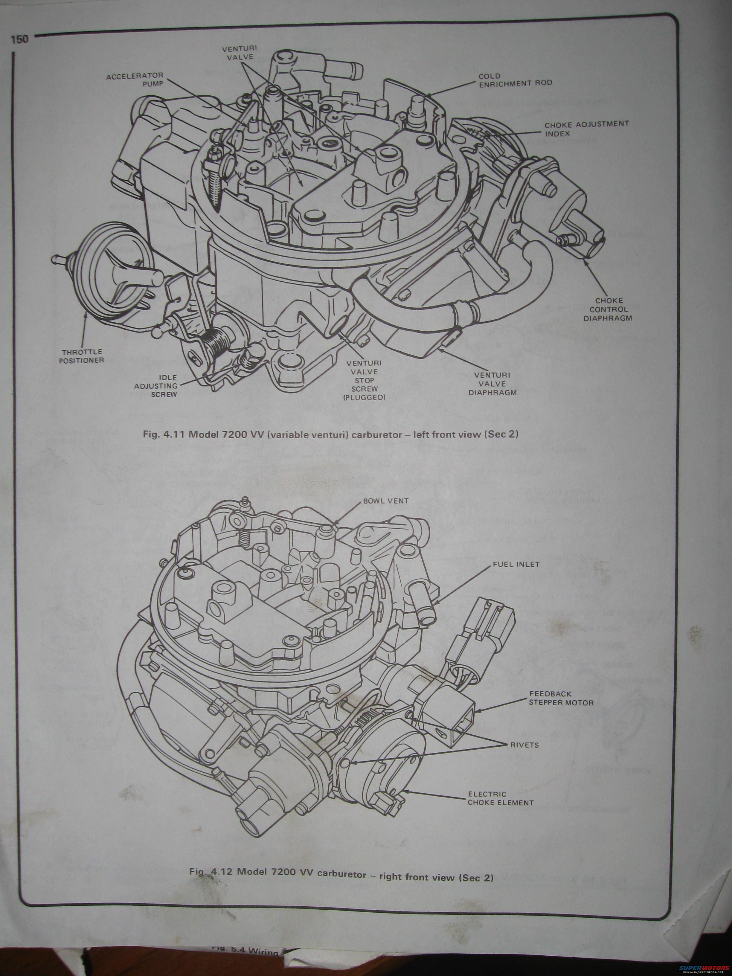
Ford 7200 VV Variable Venturi Carburetor Diagram - Component Callouts (Manual Pg 150)
Reference · 1980-1986 BroncoAll 28 manual pages
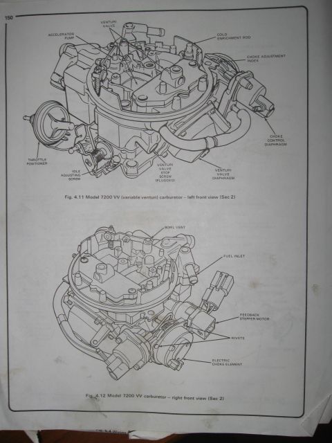
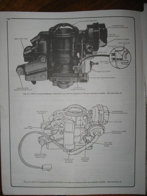
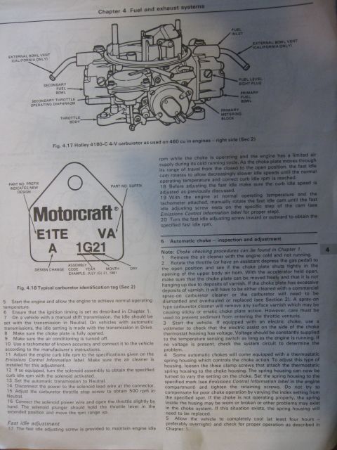
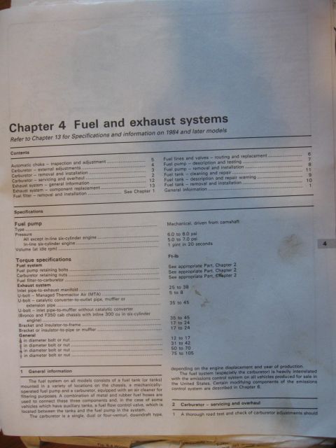
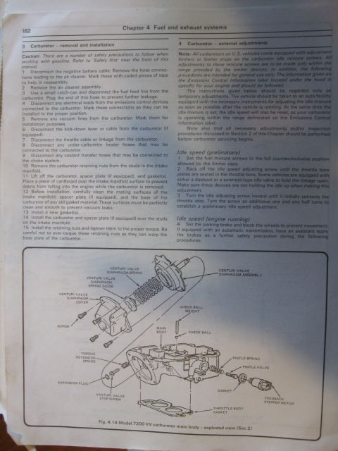

Service manual page showing labeled left- and right-front views of a Model 7200 VV variable-venturi carburetor.
Part of 1980-1986 Ford Bronco Manual Pages
This is page 150 from an automotive repair manual (Haynes-style) showing two labeled exploded/isometric line drawings of the Ford Motorcraft Model 7200 VV (variable venturi) carburetor. Figure 4.11 presents a left front view identifying major external components: the venturi valve, accelerator pump, cold enrichment rod, choke adjustment index, choke control diaphragm, venturi valve diaphragm, venturi valve stop screw (plugged), idle adjusting screw, and throttle positioner. Figure 4.12 presents a right front view identifying the bowl vent, fuel inlet, feedback stepper motor, rivets, and electric choke element. Both figures reference Section 2 of the manual's fuel system chapter. The page is useful to anyone servicing or identifying parts on a 7200 VV feedback carburetor, such as locating the idle adjusting screw for idle setting, understanding where the electric choke element and choke control diaphragm are mounted, and identifying the feedback stepper motor connector on the fuel-injection-era emissions feedback carburetor. A partially visible caption at the bottom edge references 'Fig. 5.4 Wiring,' indicating the next page continues into a wiring diagram section. No year, engine, or vehicle model applicability is stated on this page itself.
Is this accurate? Sign in to help verify it.
Frequently asked questions
- What carburetor is shown in these diagrams?
- The Model 7200 VV (variable venturi) carburetor, shown in left front view (Fig. 4.11) and right front view (Fig. 4.12).
- Where is the idle adjusting screw on the 7200 VV carburetor?
- Fig. 4.11 shows the idle adjusting screw on the lower left front of the carburetor, near the throttle positioner.
- What components are identified on the right front view of the 7200 VV?
- Fig. 4.12 labels the bowl vent, fuel inlet, feedback stepper motor, rivets, and electric choke element.
- Is the venturi valve stop screw adjustable?
- The diagram labels it as 'Venturi Valve Stop Screw (Plugged),' indicating it is sealed/plugged.
- What choke-related parts are shown on the 7200 VV carburetor?
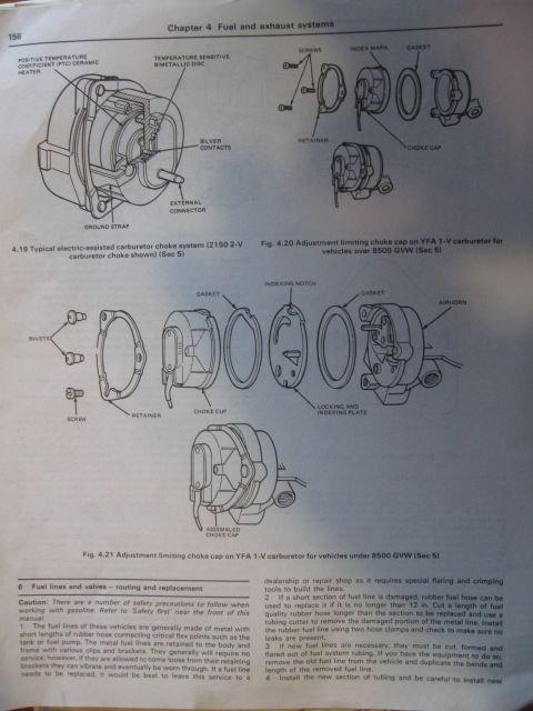
- The cold enrichment rod, choke adjustment index, choke control diaphragm (Fig. 4.11), and the electric choke element (Fig. 4.12).
No comments yet.