Home/
Registry/
Ford/
Bronco/
1980-1986/
“Still Pending”/
Photo
supermotors.net/registry/media/825054
Ford Charging System Wiring Diagram - Electronic Regulator, Warning Light & Ammeter
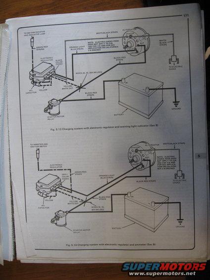
Two charging-system wiring diagrams (warning-light and ammeter versions) showing alternator, electronic regulator, starter relay and battery with circuit wire color codes.
This is page 171 of a printed automotive service manual showing two charging system wiring diagrams. Figure 5.13 depicts a charging system with an electronic voltage regulator and a warning light indicator (referencing Section 9), while Figure 5.14 shows the same charging system variant with an electronic regulator and an ammeter. Both diagrams illustrate the alternator (with STATOR, BAT, FIELD, and GRD terminals), electronic regulator, RFI capacitor, starter motor relay, battery, and ground connections. Wire color codes are labeled throughout, including white-black stripe, green-red stripe, orange-light blue stripe, black-red stripe, yellow, and yellow with white dot; welded wire junctions are called out (wires 36, 38, 38A in Fig. 5.13; 36, 33, 38A in Fig. 5.14). The warning-light version uses a black color-coded regulator connected to a 500 ohm resistor and indicator lamp, while the ammeter version uses a gray color-coded regulator connected to the ammeter and ignition switch. Both diagrams note that the electric choke feed does not apply to the 3.8L (232 CID) V-6 or to EEC applications on California V-8 engines. A reader can use this page to trace charging circuit wiring, identify regulator type by connector color, and verify wire colors during diagnosis.
Is this accurate? Sign in to help verify it.
Frequently asked questions
- What is the difference between the two charging system diagrams shown?
- Fig. 5.13 shows the charging system with an electronic regulator and a warning light indicator (using a black color-coded regulator connected to a 500 ohm resistor and indicator lamp), while Fig. 5.14 shows the system with an electronic regulator and an ammeter (using a gray color-coded regulator connected to the ammeter and ignition switch).
- What wire colors are used in this charging system?
- Labeled wire colors include white-black stripe, green-red stripe(s), orange-light blue stripe, black-red stripe, yellow, and yellow with a white dot.
- Which engines do not get the electric choke feed?
- The note states the electric choke feed does not apply to the 3.8L (232 CID) V-6 and for EEC applications on California V-8 engines.
- How do I tell the warning-light regulator from the ammeter regulator?
- The regulator for the warning light system is black color coded; the regulator for the ammeter system is gray color coded.
- What alternator terminals are shown in the diagrams?
- The alternator is shown with STATOR, BAT, FIELD, and GRD terminals.
Comments
More from this build










No comments yet.