Ford RFI Suppression Capacitor Install - Ignition Coil 4.9L 5.0L 5.8L 7.5L MFI

Reference · 1987-1991 BroncoAll 95 service procedures


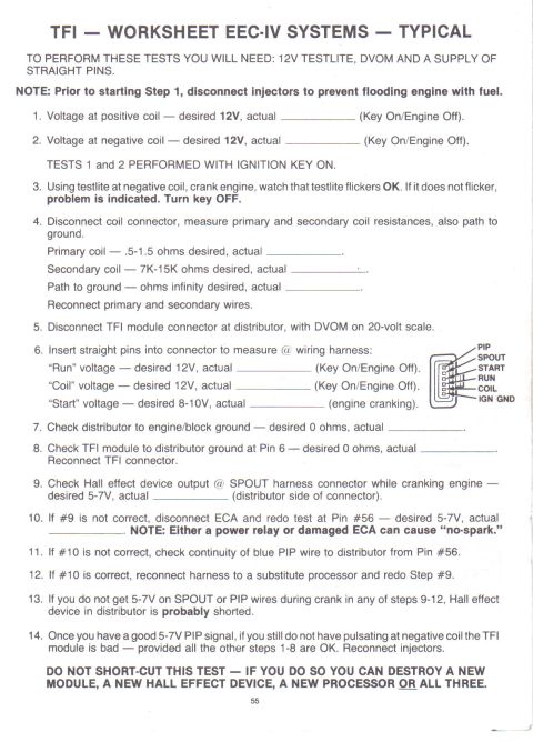


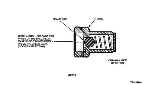
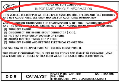
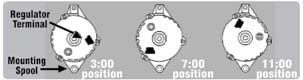










Ford illustrations for installing the capacitor to the coil assembly and ignition coil on 5.0L, 5.8L, 4.9L and 7.5L engines.
Part of 1987-1991 Ford Bronco Service Procedures
This document is a four-panel illustrated service reference showing the installation of an RFI (radio frequency interference) suppression capacitor to the ignition coil on Ford MFI (multiport fuel injection) engines. Each panel is a line drawing of the coil/capacitor assembly with numbered callouts (1 through 7 across the panels) identifying components, though no legend defining the callout numbers is included in this scan. The four installation variants covered are: capacitor assembly to coil assembly for the 5.0L (MFI) engine; capacitor assembly to coil assembly for the 5.8L (MFI) engine; capacitor to ignition coil for the 4.9L (MFI) engine when equipped with a 75 amp alternator and manual transmission; and capacitor to ignition coil for the 7.5L (MFI) engine. The figure carries Ford illustration reference number K20720-B. A reader can learn the correct mounting location and orientation of the suppression capacitor relative to the ignition coil and bracket for each of these four engine applications. The document itself does not state a model year or vehicle model, but the engine list (4.9L, 5.0L, 5.8L, 7.5L MFI) corresponds to Ford truck powertrains, consistent with its filing under a Ford Bronco ignition-system album.
Is this accurate? Sign in to help verify it.
Frequently asked questions
- Where does the RFI suppression capacitor mount on a Ford 5.0L or 5.8L MFI engine?
- The diagrams show the capacitor assembly installing directly to the coil assembly on both the 5.0L (MFI) and 5.8L (MFI) engines, with numbered callouts indicating the mounting hardware and wiring routing.
- Does the 4.9L engine capacitor installation apply to all configurations?
- No. The illustration for the 4.9L (MFI) engine specifically applies to vehicles with a 75 amp alternator and manual transmission.
- Which engines are covered in this capacitor installation diagram?
- Four MFI engines are covered: 5.0L, 5.8L, 4.9L (with 75 amp alternator and manual transmission), and 7.5L.
- What is the figure reference number on this diagram?
- The illustration is marked K20720-B.






No comments yet.