Ford EEC-IV TFI Module Diagnostic Worksheet - Ignition No-Spark Test Steps
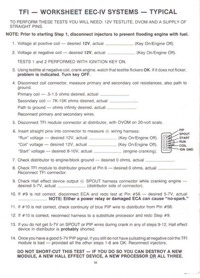
TFI/EEC-IV ignition test worksheet listing coil voltages and resistance targets (primary 0.5-1.5 ohm, secondary 7K-15K ohm, START 8-10V) and step-by-step no-spark diagnosis.
This document is a 14-step diagnostic worksheet for testing the Thick Film Ignition (TFI) module and related ignition components on Ford EEC-IV engine management systems. It lists required tools (12V test light, DVOM, straight pins) and warns to disconnect the fuel injectors before starting to prevent flooding the engine. The steps guide the technician through checking voltage at the positive and negative coil terminals (12V desired, Key On/Engine Off), watching for test-light flicker at the negative coil during cranking, and measuring ignition coil resistances: primary coil .5-1.5 ohms, secondary coil 7K-15K ohms, and infinite ohms path to ground. It then covers back-probing the TFI module harness connector with straight pins to verify Run (12V), Coil (12V), and Start (8-10V) voltages, with a connector pin diagram labeling PIP, SPOUT, START, RUN, COIL, and IGN GND. Further steps check distributor-to-engine ground, TFI-to-distributor ground at Pin 6, Hall effect device output at the SPOUT connector during cranking (5-7V desired), and follow-up tests at ECA Pin #56, including checking the blue PIP wire continuity and substituting a processor. The worksheet concludes with logic for condemning the Hall effect device or the TFI module, and a bold warning not to shortcut the test to avoid destroying a new module, Hall effect device, or processor.
Is this accurate? Sign in to help verify it.
Frequently asked questions
- What tools do I need to perform the TFI ignition tests on a Ford EEC-IV system?
- A 12V test light, a DVOM (digital volt-ohm meter), and a supply of straight pins for back-probing the connector.
- What are the desired resistance values for the ignition coil?
- Primary coil: .5-1.5 ohms; secondary coil: 7K-15K ohms; path to ground: infinite ohms.
- What voltages should be present at the TFI harness connector?
- "Run" voltage 12V and "Coil" voltage 12V with Key On/Engine Off, and "Start" voltage 8-10V while cranking the engine.
- What voltage should the Hall effect device output at the SPOUT connector while cranking?
- 5-7V, measured on the distributor side of the connector. If not present, disconnect the ECA and retest at Pin #56, also desired 5-7V.
- Why should the injectors be disconnected before starting the test?
- The worksheet says to disconnect the injectors prior to Step 1 to prevent flooding the engine with fuel; they are reconnected at Step 14.
- What can happen if the test procedure is shortcut?
- The worksheet warns you can destroy a new TFI module, a new Hall effect device, a new processor, or all three.
Comments
More from this build














No comments yet.