1994-Up Ford 5.0L Spark Plug Wire Routing Diagram & Firing Order 1-3-7-2-6-5-4-8

Reference · 1987-1991 BroncoAll 95 service procedures
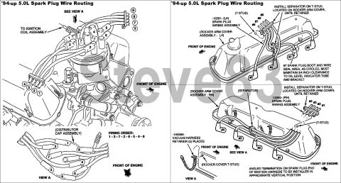
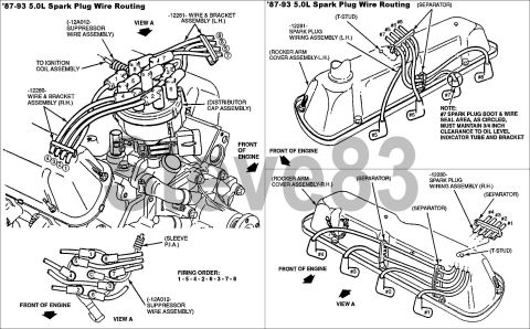









Ford service diagram: '94-up 5.0L spark-plug wire routing (T-stud type) showing firing order 1-3-7-2-6-5-4-8, LH/RH spark plug wiring assemblies 12281, separator T-stud installation and 3/4 inch clearance note for #7 plug boot.
Part of 1987-1991 Ford Bronco Service Procedures
This is a two-panel Ford service illustration showing spark plug wire routing for the 1994-and-later ('94-up) 5.0L V8 engine. The left panel shows an overall engine view with the distributor cap assembly, the wire to the ignition coil assembly, numbered plug wire positions (cylinders 1-8), and a 'View A' detail of the distributor cap terminal layout. The firing order is stated as 1-3-7-2-6-5-4-8. The right panel shows detailed routing along each rocker arm cover: the left-hand (LH) bank uses spark plug wiring assembly -12281- carrying wires #5, #6, #7, and #8, while the right-hand (RH) bank uses wiring assembly -12280- carrying wires #1, #2, #3, and #4. Callouts instruct installing wire separators on the T-studs located on the rocker arm covers until retained, and note that the #7 spark plug boot and wire seal area must maintain 3/4 inch clearance to the oil level indicator (dipstick) tube and bracket. Part -14A594- vacuum harness retainer is used in two places, and the angled termination on the spark plug end of the ignition harness is to be installed in an approximately vertical position. Front-of-engine arrows orient each view.
This document covers 1994-up, which may differ from this 1990 Ford Bronco.
Is this accurate? Sign in to help verify it.
Frequently asked questions
- What is the firing order for the '94-up Ford 5.0L engine?
- The diagram states the firing order is 1-3-7-2-6-5-4-8.
- Which spark plug wiring assembly goes on each side of the engine?
- The LH (left-hand) rocker arm cover uses spark plug wiring assembly -12281- (wires #5-#8), and the RH (right-hand) side uses assembly -12280- (wires #1-#4).
- How much clearance must the #7 spark plug boot have?
- The #7 spark plug boot and wire seal area must maintain 3/4 inch clearance to the oil level indicator tube and bracket.
- Where are the wire separators installed?
- Separators are installed on the T-studs located on the rocker arm covers until retained.
- How should the spark plug ends of the ignition harness be positioned?
- The angled termination on the spark plug end of the ignition harness is to be installed in an approximate vertical position.






No comments yet.