Home/
Registry/
Ford/
Mustang/
1979-1993/
1990 Ford Mustang/
Photo
supermotors.net/registry/media/839150
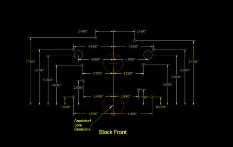
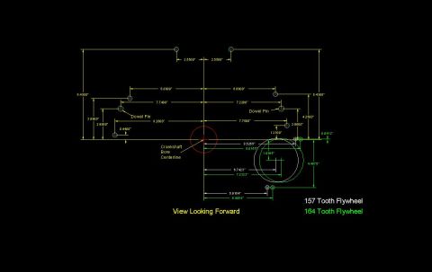
Small Block Ford Bellhousing/Block Bolt Pattern Blueprint - Dimensions in Inches
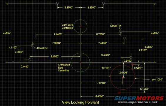
Dimensioned CAD blueprint showing cam-bore and crankshaft-bore centerlines, dowel pins, and bore diameter, view looking forward.
This document is a CAD-style dimensional blueprint titled "View Looking Forward," showing the bolt hole, dowel pin, and bore locations on the face of an engine block or bellhousing pattern. All positions are dimensioned in inches relative to two reference lines: the cam bore centerline (vertical) and the crankshaft bore centerline (horizontal). The drawing locates two dowel pins, multiple bolt holes, the cam bore, the crankshaft bore, and a large 4.1000" diameter circle (likely a starter or accessory opening) positioned 7.0748" to the right of the vertical centerline and 2.5130" below the crankshaft centerline. Key dimensions include top bolt holes 3.8500" either side of centerline and 9.9600" above the crank centerline; dowel pins at 6.7600" right and roughly 7.4400"/7.9900" left of centerline at heights of 4.1100", 5.2500", and 2.8000"; and lower holes at 8.4500" left and 8.4700" right of centerline. Additional dimensions include 8.7181", 0.8400", 0.3607", 0.4400", 5.1262", and 6.4696". A reader can use this drawing to fabricate an adapter plate, verify bolt pattern compatibility, or locate dowel pins on a matching engine block face. Uploaded to a 1990 Ford Mustang gallery alongside small block Ford block pattern drawings.
Is this accurate? Sign in to help verify it.
Frequently asked questions
- How far apart are the top two bolt holes on this pattern?
- Each top bolt hole is 3.8500" from the cam bore centerline (7.7000" apart), located 9.9600" above the crankshaft bore centerline.
- Where are the dowel pins located on this pattern?
- One dowel pin is 6.7600" to the right of the cam bore centerline, and another is on the left side at 4.1100" above the crankshaft centerline (with left-side dimensions of 7.4400" and 7.9900" shown for the upper-left holes).
- What is the diameter of the large circle at the lower right of the drawing?
- It is 4.1000" in diameter, centered 7.0748" right of the cam bore centerline and 2.5130" below the crankshaft bore centerline.
- What reference lines are all dimensions measured from?
- Dimensions are referenced to the cam bore centerline (vertical) and the crankshaft bore centerline (horizontal), as viewed looking forward.
Comments
More from this build
No comments yet.