Home/
Registry/
Ford/
Mustang/
1979-1993/
1990 Ford Mustang/
Photo
supermotors.net/registry/media/842551
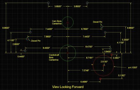
Small Block Ford Rear Bellhousing Bolt Pattern Blueprint - 157 & 164 Tooth

Dimensioned CAD blueprint of crankshaft and dowel-pin locations comparing 157-tooth and 164-tooth flywheel positions, view looking forward.
This document is a CAD-style blueprint/dimensional drawing of the rear bellhousing bolt pattern for a Small Block Ford engine, shown in a 'View Looking Forward' orientation. All dimensions are referenced from the crankshaft bore centerline, which is highlighted with a red circle. The drawing locates each bellhousing bolt hole with horizontal and vertical dimensions (e.g., top bolts at 2.5500" either side of centerline and 8.4300" up; lower bolts at 8.2600" and 7.7500" out), and identifies the two dowel pin locations at 7.7400" (left) and 7.2200" (right) horizontally. The drawing also overlays the starter/starter-nose opening location for two different flywheel sizes: dimensions in white apply to a 157-tooth flywheel (e.g., 8.5255", 6.7423", 5.9154") and dimensions in green apply to a 164-tooth flywheel (e.g., 9.0155", 7.2323", 6.4054", 4.4678", 1.9365", 0.0412"). A reader can use this diagram to lay out or verify a Small Block Ford bellhousing bolt pattern, locate dowel pins, and determine starter placement differences between 157- and 164-tooth flywheel applications. The document itself gives no year, part numbers, or model applicability text.
Is this accurate? Sign in to help verify it.
Frequently asked questions
- What are the dowel pin locations on the Small Block Ford bellhousing pattern?
- The drawing shows the left dowel pin at 7.7400" horizontally from the crankshaft bore centerline and the right dowel pin at 7.2200" horizontally, with vertical dimensions of 3.8800"/2.9000" (left) and 4.2500"/2.9000" (right) shown in the same area.
- What reference point are the bellhousing dimensions measured from?
- All dimensions are referenced from the crankshaft bore centerline, which is labeled and marked with a red circle in the drawing.
- How does starter location differ between 157-tooth and 164-tooth flywheels?
- The drawing shows two starter locations: white dimensions (8.5255", 6.7423", 5.9154") apply to a 157-tooth flywheel, while green dimensions (9.0155", 7.2323", 6.4054", 4.4678", 1.9365", 0.0412") apply to a 164-tooth flywheel.
- Where are the top bellhousing bolt holes located?
- The two top bolt holes are each 2.5500" horizontally from the crankshaft bore centerline and 8.4300" vertically per the side dimensions.
- What orientation is the drawing shown in?
- It is labeled 'View Looking Forward,' i.e., viewing the rear of the block/bellhousing face looking toward the front of the engine.
Comments
More from this build



No comments yet.