Home/
Registry/
Ford/
Mustang/
1979-1993/
1990 Ford Mustang/
Photo
supermotors.net/registry/media/817982
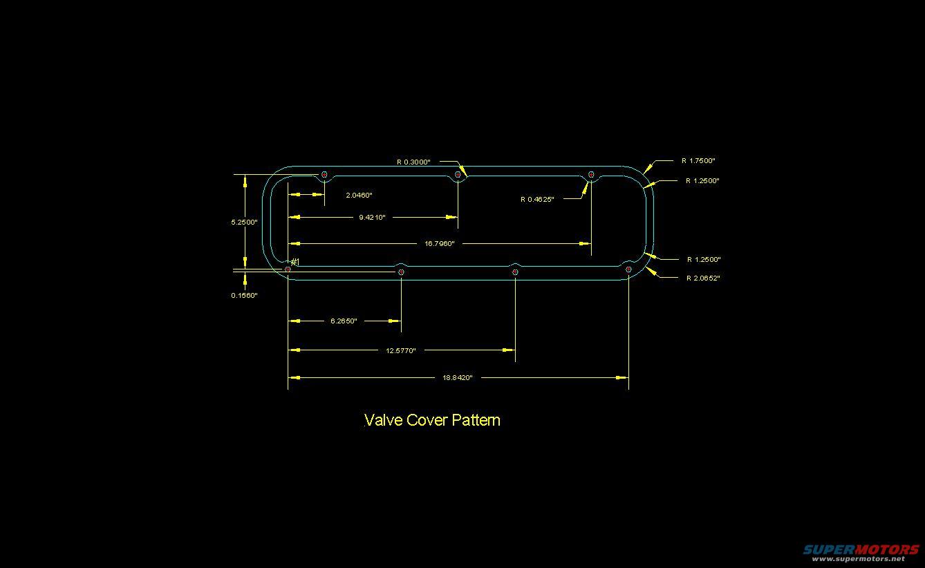
Ford Small Block Valve Cover Bolt Pattern Blueprint - Dimensions & Radii
Reference · 1979-1993 MustangAll 10 blueprints
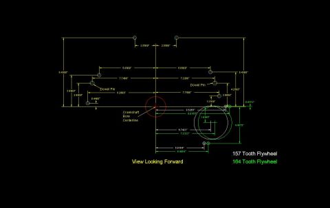
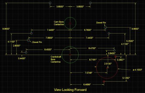
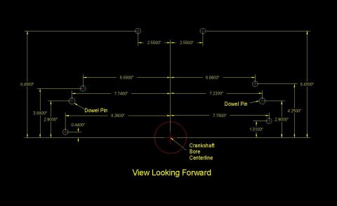
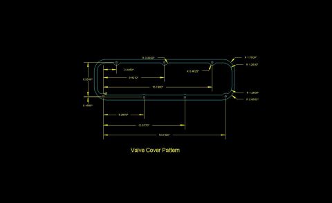
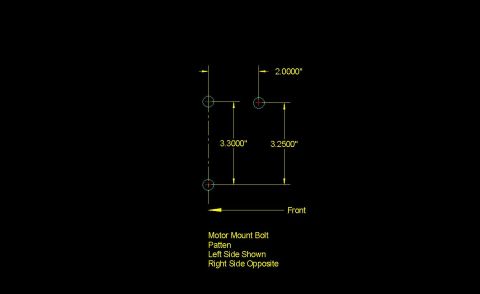
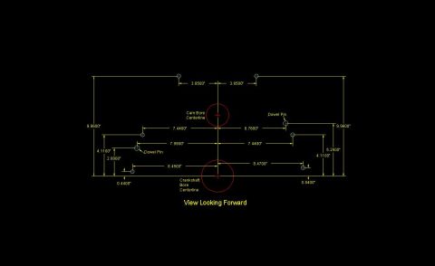
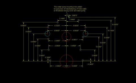
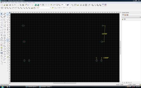
Dimensioned CAD blueprint of a valve-cover pattern showing bolt-hole spacing, radii, and overall measurements.
Part of 1979-1993 Ford Mustang Blueprints
This document is a CAD-style blueprint titled "Valve Cover Pattern," showing the bolt hole layout and outline geometry for a valve cover gasket surface. The drawing depicts an elongated rounded-rectangle pattern with six bolt holes (three along the top edge, three along the bottom edge, plus a reference hole marked #1 at the bottom-left). Horizontal dimensions locate the top-row holes at 2.0460", 9.4210", and 16.7960" from the left reference, and the bottom-row holes at 6.2650", 12.5770", and 18.8420" from hole #1. The vertical distance between the two bolt rows is 5.2500", with a 0.1560" offset dimension at the bottom-left. Corner and profile radii are called out as R 1.7500", R 1.2500" (two locations), R 2.0652", R 0.3000", and R 0.4625". A fabricator or machinist could use these dimensions to lay out a valve cover, gasket, or flange matching this pattern. The document itself contains no year, make, model, or part number information; it was uploaded to a 1990 Ford Mustang gallery alongside other small-block Ford engine pattern drawings.
Is this accurate? Sign in to help verify it.
Frequently asked questions
- What is the overall bolt hole span of the valve cover pattern?
- The longest dimension shown is 18.8420" between the outermost bottom-row bolt holes, measured from hole #1.
- What is the vertical distance between the top and bottom rows of bolt holes?
- The drawing shows 5.2500" between the top and bottom bolt hole rows.
- What are the bolt hole spacings along the top edge?
- Top-row holes are located at 2.0460", 9.4210", and 16.7960" from the left reference point.
- What corner radii are specified on the valve cover pattern?
- Callouts show R 1.7500", R 1.2500" (in two places), R 2.0652", R 0.3000", and R 0.4625".
- How many bolt holes does the pattern show?
- The drawing shows six or seven small holes: three dimensioned along the top edge and holes along the bottom edge dimensioned from a hole labeled #1.

No comments yet.