Home/
Registry/
Ford/
Mustang/
1979-1993/
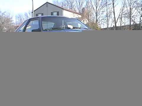
1990 Ford Mustang/
Photo
supermotors.net/registry/media/816192
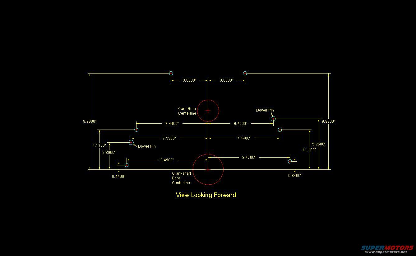
Small Block Ford Rear Block Face Blueprint - Bellhousing Hole & Dowel Pin Dims
Reference · 1979-1993 MustangAll 10 blueprints
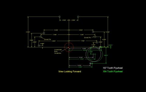
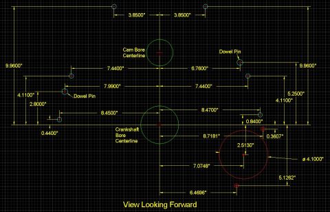
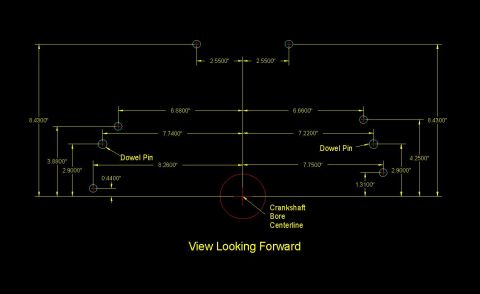
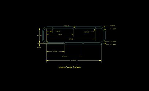
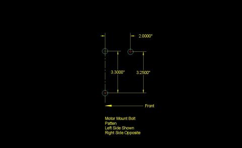
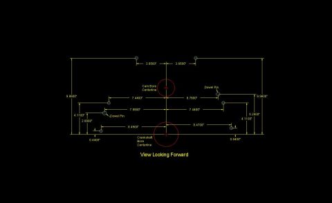
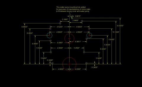
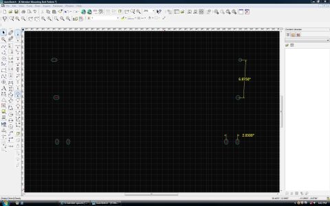
Dimensioned CAD blueprint showing cam-bore and crankshaft-bore centerlines and dowel-pin locations, view looking forward.
Part of 1979-1993 Ford Mustang Blueprints
This document is a CAD-style dimensional blueprint (yellow linework on black background) showing the rear face bolt/dowel hole pattern of an engine block, labeled 'View Looking Forward.' Based on the album context (filename 'True Block Rear.JPG' alongside 'SbFord Rear Bellhousing Pattern' and 'Small Block Ford Block Front'), it depicts the rear bellhousing mating surface hole locations. The drawing marks the Cam Bore Centerline and Crankshaft Bore Centerline as red circles, and identifies two Dowel Pin locations. All hole positions are dimensioned in inches relative to the vertical centerline and the crankshaft centerline plane: top holes are 3.8500" either side of centerline and 9.9600" above the crank plane; middle-row holes are at 7.4400", 6.7600", 7.9900", and 7.4400" horizontally with heights of 4.1100", 2.8000", 5.2500", and 4.1100"; lower holes sit 8.4500" and 8.4700" from centerline with 0.4400" and 0.8400" offsets. A reader can use these coordinates to locate or verify bellhousing bolt holes and dowel pin positions when fabricating adapters, checking block machining, or laying out a transmission adapter plate. No year, part numbers, or explicit engine identification appear on the drawing itself.
Is this accurate? Sign in to help verify it.
Frequently asked questions
- What does this blueprint show?
- It shows the rear face hole pattern of an engine block ('View Looking Forward'), with dimensioned locations for bolt holes and two dowel pins relative to the cam bore and crankshaft bore centerlines.
- How far apart are the top two holes?
- Each top hole is 3.8500" from the vertical centerline, so they are 7.7000" apart, and both are 9.9600" above the crankshaft centerline plane.
- Where are the dowel pins located?
- The left dowel pin is 7.9900" left of the vertical centerline; the right dowel pin is 6.7600" right of the centerline. Adjacent height dimensions on the drawing include 4.1100" (left) and 5.2500" (right) above the crankshaft centerline plane.
- What are the positions of the lowest bolt holes?
- The lower-left hole is 8.4500" from the vertical centerline with a 0.4400" offset dimension; the lower-right hole is 8.4700" from centerline with a 0.8400" offset dimension.
- What reference lines are marked on the drawing?
- The Cam Bore Centerline and the Crankshaft Bore Centerline are marked with red circles on the vertical centerline of the block face.
No comments yet.