Home/
Registry/
Ford/
Mustang/
1979-1993/
1990 Ford Mustang/
Photo
supermotors.net/registry/media/817981
Small Block Ford Motor Mount Bolt Pattern Diagram - Dimensions (1990 Mustang)

Reference · 1979-1993 MustangAll 10 blueprints
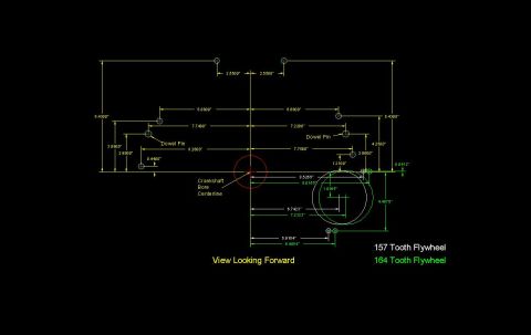
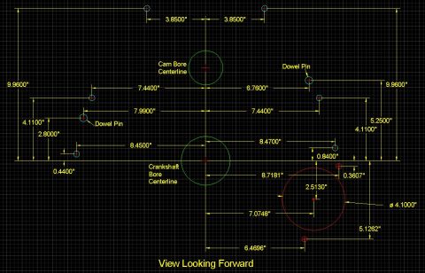
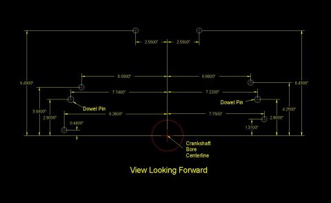
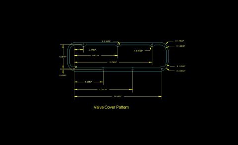
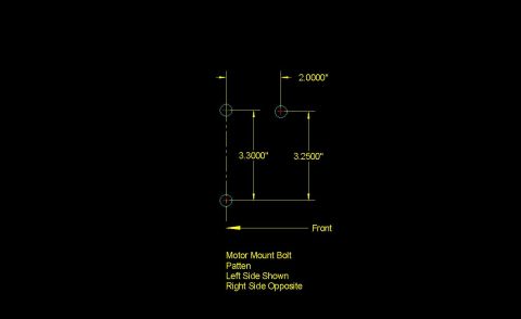
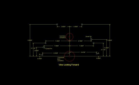
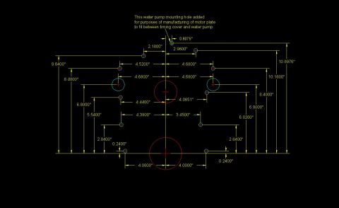
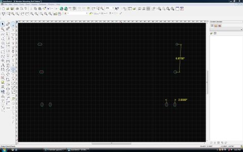
Dimensioned CAD blueprint of a motor-mount bolt pattern, left side shown with right side opposite.
Part of 1979-1993 Ford Mustang Blueprints
This is a CAD-style blueprint diagram showing the motor mount bolt pattern for an engine block, uploaded to the gallery of a 1990 Ford Mustang. The drawing depicts three bolt holes (shown as circled crosshair markers) on the left side of the block, with the note that the right side is opposite (mirror image). Dimensions given: the upper rear bolt hole is offset 2.0000" horizontally from the front bolt-hole axis line; the vertical spacing between the front upper hole and the lower hole is 3.3000"; the vertical spacing between the rear upper hole and the lower hole is 3.2500". An arrow labeled "Front" indicates the forward direction of the engine (pointing toward the vertical centerline through two of the holes). The caption reads "Motor Mount Bolt Patten [sic] / Left Side Shown / Right Side Opposite." A reader can use this diagram to locate or fabricate engine mounts, verify bolt-hole spacing on a block, or design adapter plates. The document contains no part numbers, year, model, or engine designation, though companion files in the album reference small block Ford blocks.
Is this accurate? Sign in to help verify it.
Frequently asked questions
- What are the motor mount bolt hole spacing dimensions shown?
- The diagram shows 3.3000" vertical spacing between the front upper hole and the lower hole, 3.2500" between the rear upper hole and the lower hole, and a 2.0000" horizontal offset for the rear upper hole from the front hole axis.
- Does this diagram show both sides of the engine block?
- No. It shows the left side only, with a note stating 'Right Side Opposite,' meaning the right side is a mirror image of the pattern shown.
- How many bolt holes are in the motor mount pattern shown?
- Three bolt holes are shown: two upper holes (front and rear) and one lower hole.
- How is the orientation of the diagram indicated?
- An arrow labeled 'Front' points toward the front of the engine, aligned with the vertical centerline through the front bolt holes.

No comments yet.